
Principles of RC filtering
When high-frequency noise has to be removed, a filter must be added in series with the signal. This causes the high-frequency noise to be attenuated but some side effects are introduced and, in some cases, they cannot be neglected. In this article, many configurations are analyzed and their respective transfer functions are found.
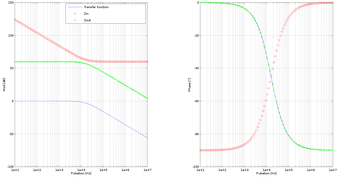
Single pole RC
This is the simplest way to filter out high-frequency noise from your signal.
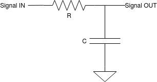
$$H(s) = \frac{1}{1+sCR} \quad \to \quad f_{-3dB}=\frac{1}{2\pi RC}$$ $$|H(s)| = \frac{1}{\sqrt{1+\omega^2R^2C^2}}$$ $$\angle H(s) = atan(-\omega RC)$$ $$Z_{IN} = R+\frac{1}{sC}$$ $$Z_{OUT} = \frac{R}{1+sCR}$$
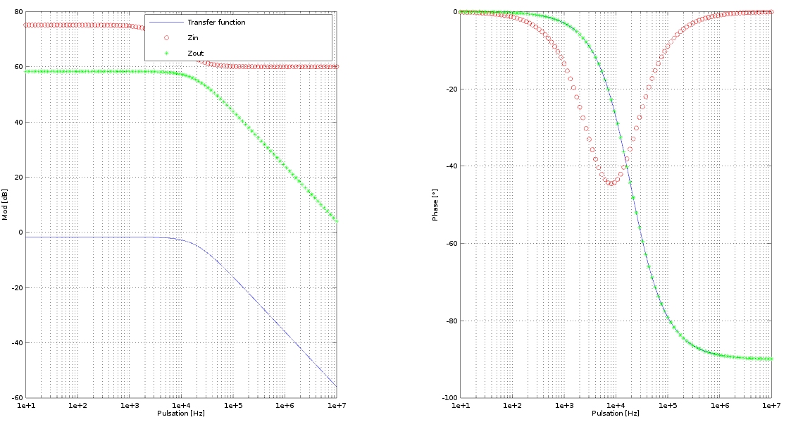
Single pole RC with voltage divider
If you need to scale down a signal to the voltage levels supported by the chosen GPIO pin or the ADC pin, then use this configuration.
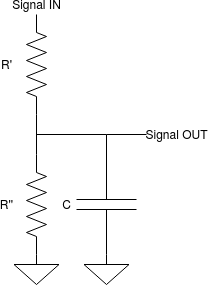
$$H(s) = \frac{R''}{sCR'R''+R'+R''}\quad \to \quad f_{-3dB}=\frac{1}{2\pi C(R'//R'')}$$ $$|H(s)| = \frac{R''}{(R''+R')\sqrt{1+(\omega C (R'//R''))^2}}$$ $$\angle H(s) = atan(-\omega C (R'//R''))$$ $$Z_{IN} = R'+\frac{R''}{1+sCR''}$$ $$Z_{OUT} = \frac{R' R''}{sCR'R''+R'+R''}$$
Single pole RC with voltage divider - variant
Sometimes you need some extra filtering and extra overload protection for the input pin of the receiving device: to further reduce the input current in the pin, you can use an additional series resistance.

$$\alpha = RR''+R'R''+RR'$$ $$\beta = R'+R''$$ $$H(s) = \frac{R''}{sC(RR''+R'R''+RR')+R'+R''}\quad \to \quad f_{-3dB}=\frac{R'+R''}{2\pi C(RR''+R'R''+RR')}$$ $$|H(s)| = \frac{R''\sqrt{\beta^2 - \omega^2 C^2 \alpha^2}}{\beta^2 + \omega^2 C^2 \alpha^2}$$ $$Z_{IN} = R'+\frac{R''(sCR+1)}{1+sC(R''+R)}$$ $$Z_{OUT} = \frac{R+R'//R''}{1+sC(R+R'//R'')}$$
Double pole RC
Use this configuration when you want to filter out noise at -40dB/dec. This configuration is also often used to get an analog value with reduced ripple starting from a variable duty cycle frequential signal.

$$\alpha = C'C''R'R''$$ $$\beta = C'R'+C''R'+C''R''$$ $$H(s) = \frac{1}{1+s\beta+s^2\alpha}$$ $$|H(s)| = \frac{1}{\sqrt{(1-\omega^2\alpha)^2+(\omega\beta)^2}}$$ $$\angle H(s) = atan\bigl(\frac{-\omega \beta}{1-\omega^2 \alpha}\bigr)$$ $$Z_{IN} = R'+\frac{sC''R''+1}{s(sC'C''R''+(C'+C''))}$$ $$Z_{OUT} = \frac{sC'R' R''+R'+R''}{1+s\beta+s^2\alpha}$$
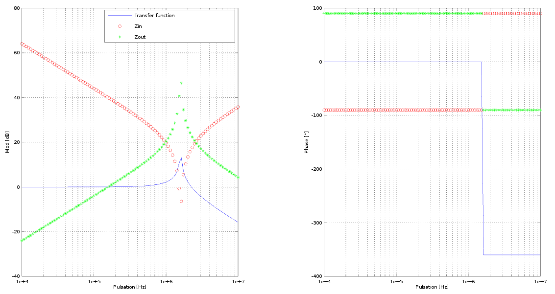
Double pole LC
LC filters are used when a very low input impedance is required for the signal. These filters are used also for power supplies, in front of both linear and switching converters.
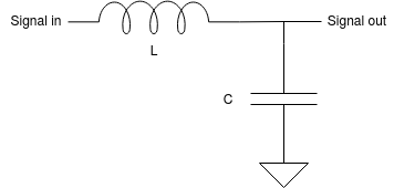
$$H(s) = \frac{1}{1+s^2 L C}\quad \to \quad f_{-6dB}=\frac{1}{2\pi \sqrt{LC}}$$ $$Z_{IN} = sL + \frac{1}{sC}$$ $$Z_{OUT} = \frac{sL}{1 + s^2 LC}$$
Share this page


Comments
Be polite and respectful in the comments section. In case of doubts, read this before posting.