➔ Index of ⦁ Linear Regulators ⦁
Linear regulators - Introduction
What is a linear regulator, pros and cons, internal scheme
Linear regulators working principle
A linear regulator is a DC-DC voltage regulator based on a pass device which, ideally, can keep voltage constant at its output, under different load and line conditions, so that Vout < Vin and Vout constant in a defined loading region (if the load is too high, the linear regulator could fail to keep the output voltage constant).
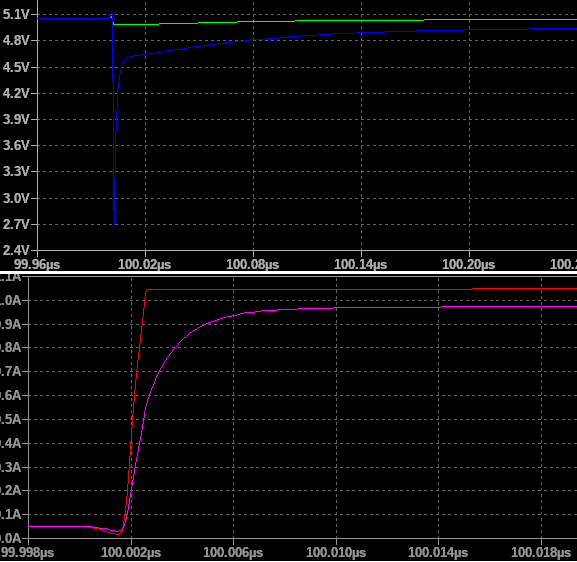
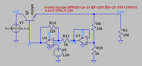
The basic linear regulator circuit is pretty simple but then we will see that also the simplest configuration hides potential issues and instabilities that must be compensated.
LDO
LDO means Low Drop Out: it is a particular type of linear regulator which can operate when Vout ~ Vin too: today, almost all linear regulators are LDOs.
Linear regulators pros
Linear regulators have a lot of good features and for these reasons, they are still used in many applications. As the definition says, they are linear by nature so we don't need to linearize their behaviour around a working point and, in the real world, we don't have all those bad aspects of switching converters (EMI, switching node ringing, input and output ripple, complex control loop, high sensitivity on stray parameters, ...) - we need to use the small signal analysis around the working point to extract the return ratio function and study stability; moreover, we will see that some parameters change under different external condition, affecting thus not only the small signal model but also the bias point of the linear regulator. Linear regulators, moreover, provide very stable output voltage, with low output ripple (no ripple if the input is properly filtered), precise and, if properly compensated, temperature-independent output voltage: for all these properties linear regulators are used typically when precise voltage references are needed (signal management, references, analogue circuitry, ...).
Linear regulators cons
Linear regulators have a main drawback: power dissipation! They dissipate a lot and, commonly, their power dissipation (considering a constant passive load) can be calculated as: $$P_{diss} = V_{do}*I_{load} = (V_{in}-V_{out})*I_{load} = (V_{in}-V_{out})*\frac{V_{out}}{R_{load}}$$ From these equations we can understand that a linear regulator can only be used when low output currents are required, otherwise, we have to move to a switching regulator.
Resume
| Feature | Linear regulator | Switching regulator |
|---|---|---|
| Number of external components | + Few external components required | - Typically, inductors, switches, capacitors, and passives are required externally to the controller |
| Output voltage ripple | + Very low, dependent only on input voltage ripple | - Higher, it depends on the output capacitor, switching node behaviour, and load characteristics |
| Output voltage precision/accuracy | + Since the control loop reference signal is made of a very precise/accurate/temperature stable voltage reference, linear regulators have a very precise/accurate/temperature stable output voltage; note that tracker LDOs can have down to ±10mV to ±20mV output voltage accuracy | - Output voltage is typically set through an external voltage divider (which has an impact on the control loop too) so the output voltage will depend on the controller tolerances AND external component tolerances |
| Control scheme | + The control loop is easier, a PI controller is already a very good solution | - The control loop is made complex by the fact that the model must linearize the behaviour of a time-discontinuous function |
| Conducted emission | + Since the device is linear, no noise is generated | - Switching noise can propagate to load circuitry and to other circuitry under the same input power supply, negatively affecting their performance |
| Radiated emission | + Since the device is linear, no radiated emission is generated | - Switching node noise generates radiated emissions too; they can directly propagate through space or they can generate additional conducted common mode noise which in many cases is the cause of radiated emission |
| Power dissipation | - Power dissipation is very high across the linear device | + Power dissipation can be greatly minimized with an accurate design and component choice |
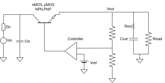
Linear regulator main building blocks
Pass device
The pass transistor in an LDO (Low Dropout) voltage regulator is a crucial component responsible for output voltage regulation. It acts as a variable resistor, adjusting its conductivity to control the current flow from the input to the output, thus stabilizing the output voltage.
The pass transistor is typically a MOSFET (Metal-Oxide-Semiconductor Field-Effect Transistor) or a BJT (Bipolar Junction Transistor), chosen for its ability to handle current and voltage while maintaining low dropout characteristics efficiently.
The design of the pass transistor is crucial for achieving low dropout voltage, high efficiency, and stable output voltage regulation. Factors such as channel resistance, threshold voltage, and transistor size are carefully considered to optimize performance and minimize power dissipation.
Controller
The control circuit in an LDO (Low Dropout) voltage regulator is responsible for monitoring the output voltage and adjusting the pass transistor to maintain a stable output voltage despite variations in input voltage or load conditions. The control circuit typically includes a voltage reference, error amplifier, feedback network, and compensation circuitry.
Voltage reference
The control circuit starts with a stable voltage reference, often a precision bandgap reference or a Zener diode. This reference voltage serves as the desired output voltage level against which the actual output voltage is compared. Here are some key aspects of the voltage reference:
- Precision and Stability The voltage reference must provide a stable and accurate reference voltage over a wide range of operating conditions. This ensures that the output voltage of the regulator remains constant and within specified tolerances.
- Temperature Stability The voltage reference should exhibit minimal sensitivity to temperature changes to maintain accuracy across different operating temperatures. Temperature-compensated voltage references or bandgap voltage references are commonly used to achieve this requirement.
- Low Dropout Voltage In low dropout voltage regulators, the voltage reference should have a low dropout voltage to minimize the difference between the input and output voltages required for regulation. This enables the regulator to operate efficiently even when the input voltage is close to the desired output voltage.
- Noise and Ripple Rejection The voltage reference should exhibit good rejection of noise and ripple present in the input voltage to ensure a clean and stable output voltage. This is particularly important for sensitive electronic circuits where noise can degrade performance.
- Current Consumption The voltage reference should consume minimal current to avoid excessive power dissipation and maximize the efficiency of the regulator.
Output capacitor
The output capacitor in an LDO (Low Dropout) voltage regulator is a critical component that contributes to the stability and performance of the regulator. When selecting an output capacitor for an LDO voltage regulator, factors such as capacitance value, equivalent series resistance (ESR), and equivalent series inductance (ESL) must be carefully considered to ensure proper performance and stability. The capacitor should have low ESR and ESL to minimize losses and impedance, thereby maximizing stability and transient response.
It serves several important functions:
- Filtering The output capacitor acts as a filter to smooth out any fluctuations or ripple in the output voltage caused by variations in load current or transient disturbances. It helps to ensure a stable and clean output voltage.
- Loop Stability The output capacitor plays a crucial role in maintaining stability in the feedback loop of the voltage regulator. It helps to compensate for the phase shift introduced by the output impedance of the regulator and the load, thus preventing oscillations or instability.
- Transient Response The output capacitor assists in providing a fast and accurate transient response to sudden changes in load current. It helps to supply additional current during transient events, reducing voltage droop and ensuring that the output voltage remains within the desired limits.
Share this page


Comments
Be polite and respectful in the comments section. In case of doubts, read this before posting.
Posted comments ⮧
Comment section still empty.
INDEX
INFO
STATISTICS
NEXT ARTICLE
CONTACTS
SHARE