
What is a comparator
A comparator is an electronic circuit able to compare two analogical input signals and to provide a boolean logic/digital output (two logic states only are allowed at its output). They have many applications (analogue to digital converters, voltage monitors, protection circuits and so on), so they need special attention. Comparators are amplifiers used with no reaction or positive reaction, so the output voltage will go to the minimum or the maximum voltage allowed by the output stage just because the component saturates; positive reaction is used to give some hysteresis to the comparator itself, so additional features that protect the circuit from fast, spurious and eventually dangerous commutations at its output.
Non-inverting comparator
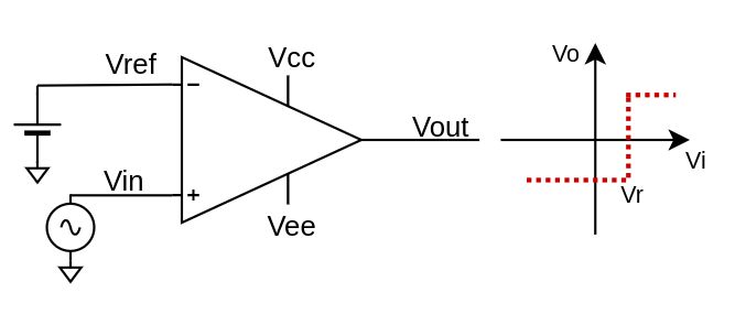
The non-inverting comparator provides a high output voltage if V+ > V-, otherwise it gives a low output voltage. The basic comparator is shown in the figure. $$V_{out} = \begin{cases} V_{OH}, \quad V_{in} \gt V_{ref} \\ V_{OL}, \quad V_{in} \lt V_{ref} \end{cases}$$
VOH is the maximum voltage and VOL is the minimum voltage at the output of the comparator, which are respectively VCC and VEE in case of rail to rail comparators; no non-ideality has been considered in this circuit, such as input bias current, input offset current, source series resistance, input offset voltage, output resistance. Moreover, this circuit is sensitive to noise since it has zero hysteresis: in case of input voltage very close to the reference voltage, a small stochastic noise superimposed could cause the output to commute very fast and this could lead to the destruction of the component (especially for push-pull output comparators) or a circuit malfunction.
Non-inverting comparator with hysteresis

The non-inverting comparator with hysteresis has two thresholds and the output commute when the most distant is reached by the input signal. $$V_{out} = \begin{cases} V_{OH}, \quad V_{in}\frac{R_f}{R_f + R_s} + V_{OL}\frac{R_s}{R_f + R_s}\gt V_{ref}\frac{R_l}{R_h + R_l} \\ V_{OL}, \quad V_{in}\frac{R_f}{R_f + R_s} + V_{OH}\frac{R_s}{R_f + R_s} \lt V_{ref}\frac{R_l}{R_h + R_l} \end{cases}$$ The thresholds are calculated as $$\begin{cases} V_{refH} = (V_{ref}\frac{R_l}{R_h + R_l} - V_{OL}\frac{R_s}{R_f + R_s})\frac{R_f + R_s}{R_f} \\ V_{refL} = (V_{ref}\frac{R_l}{R_h + R_l} - V_{OH}\frac{R_s}{R_f + R_s})\frac{R_f + R_s}{R_f} \end{cases}$$
Inverting comparator
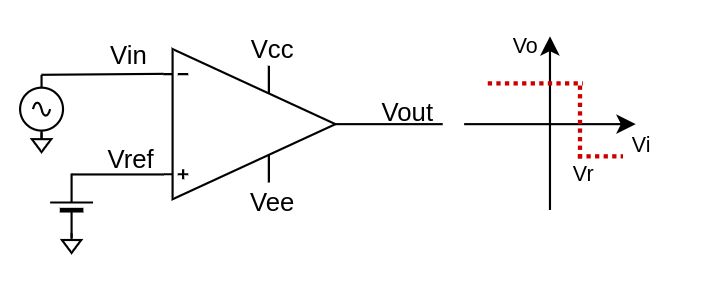
The inverting comparator provides a high output voltage if V+ < V-, otherwise it gives a low output voltage. The basic comparator is shown in the figure. $$V_{out} = \begin{cases} V_{OH}, \quad V_{in} \lt V_{ref} \\ V_{OL}, \quad V_{in} \gt V_{ref} \end{cases}$$
VOH is the maximum voltage and VOL is the minimum voltage at the output of the comparator, which are respectively VCC and VEE in case of rail to rail comparators; also here no non-ideality has been considered. This circuit is affected by low noise rejection since there is no hysteresis, exactly like the previous non-inverting one so let's add it.
Inverting comparator with hysteresis
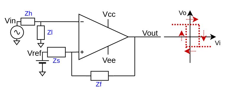
The inverting comparator with hysteresis has two thresholds and the output commute when the most distant is reached by the input signal. $$V_{out} = \begin{cases} V_{OH}, \quad V_{in}\frac{R_l}{R_l + R_h} \lt V_{refH} \\ V_{OL}, \quad V_{in}\frac{R_l}{R_l + R_h} \gt V_{refL} \end{cases}$$ The thresholds are calculated as $$\begin{cases} V_{refH} = V_{OH}\frac{R_s}{R_s + R_f} + V_{ref}\frac{R_f}{R_s + R_f} \\ V_{refL} = V_{OL}\frac{R_s}{R_s + R_f} + V_{ref}\frac{R_f}{R_s + R_f} \end{cases}$$
Share this page


Comments
Be polite and respectful in the comments section. In case of doubts, read this before posting.
Posted comments ⮧
Comment section still empty.
INDEX
INFO
STATISTICS
CONTACTS
SHARE