
Transformer model
Linear model of a transformer, with analysis of parasitic elements
Transformer
A transformer is an electrical component used to scale (up or down) the input voltage to a lower or higher value at the output, just by using a reactive element. It is made of two (or more) coupled inductances, so it can work with AC voltages and currents only; applying a DC voltage to one of the transformer coils can lead to its physical damage, making it useless. The output voltage is proportional to the input voltage using an n factor which is the ratio between the number of turns of the primary and secondary coil.
The model shown below is a linear one and doesn't account for the saturation effects of the magnetic element.
Basic transformer model
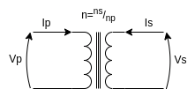
The simplest transformer model is described by the following equations $$V_s = V_p \cdot n = V_p \cdot \frac{n_s}{n_p}$$ $$I_s = I_p \cdot \frac{1}{n} = I_p \cdot \frac{n_p}{n_s}$$ The transformer just 'transforms' voltage and current, so, power is constant $$V_p I_p = V_s I_s \quad V_p I_p = V_p \frac{n_s}{n_p} I_p \frac{n_p}{n_s}$$ The ideal transformer is a lossless component acting as a voltage and current scaler.
The energy stored in the primary coil is equal to the energy stored in the secondary coil; moreover, in the ideal case, there is no power dissipation across this component, so $$E_p = \frac{1}{2}L_p I_p^2; \ E_s = \frac{1}{2}L_s I_s^2$$ Knowing that $$I_p = I_s \cdot n$$ we obtain $$\frac{1}{2}L_p I_p^2 = \frac{1}{2}L_s I_s^2 \rightarrow L_p (I_s n)^2 = L_s I_s^2$$ The relationship, for an ideal transformer, between the turn ratio n and the primary and secondary inductances is $$n = \sqrt{\frac{L_s}{L_p}}$$
DC coil resistance
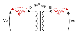
The first non-ideality we add is the parasitic wire resistance, modelling for the DC losses along primary and secondary coil wires. This leads to a secondary voltage slightly lower than the expected one $$V_p - I_p R_p = \frac{1}{n}(I_s R_s + V_s) \rightarrow V_s = n V_p - n I_p R_p + I_s R_s$$
Non ideal coupling
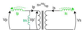
All the previous calculations have been made under the assumption of perfect coupling between the primary and secondary coil. This means that all the energy is transferred through the magnetic, and the only loss considered is the Joule effect in the windings due to DC resistance. However, part of the magnetic field generated by the primary coil does not couple to the second winding, causing an additional non-ideality, modelled with two stray inductances as shown in the picture.
The non-perfect coupling between the two coils is modelled through a coupling factor k to be multiplied by the primary inductance to find the magnetizing inductance.
Calculating the coupling factor
We said that $$n = \sqrt{\frac{L_s}{L_p}}$$ but in this case, the primary inductance is not completely coupled to the secondary one, so, only a portion of the primary inductance actively takes part in the energy transfer. The voltage at the primary side is $$V_p' = V_p \frac{(L_{p,tot}-L_{p,\sigma})}{L_{p,tot}}$$ The voltage at the secondary side, if Is - secondary side current - is very low (light load or open circuit at secondary side), is $$V_s = V_p' \sqrt{\frac{L_s}{L_{p,tot}-L_{p,\sigma}}}$$ with Ls defined as the coupled inductance on the secondary side (so total inductance - stray inductance). Now we can find the k factor $$\frac{V_s}{V_p} = \sqrt{\frac{L_s}{L_{p,tot}-L_{p,\sigma}}} \cdot \frac{(L_{p,tot}-L_{p,\sigma})}{L_{p,tot}} = \sqrt{\frac{L_s}{L_{p,tot}-L_{p,\sigma}} \cdot \frac{(L_{p,tot}-L_{p,\sigma})^2}{L_{p,tot}^2}} = $$ $$= \sqrt{\frac{L_s}{L_{p,tot}}} \cdot \sqrt{\frac{(L_{p,tot}-L_{p,\sigma})}{L_{p,tot}}} = n \cdot k$$ Remembering the methods to measure the total and the stray inductance from the primary side, we get $$k=\sqrt{1-\frac{L_{p,sec=sc}}{L_{p,sec=oc}}}$$
Core losses
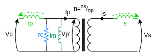
To account for the core losses we have to add a passive element across the transformer. These losses can be easily represented by a resistor placed in parallel to the magnetizing inductance, as shown in the picture.
Calculations now become more complex: since it is difficult to find the voltage at the secondary side using n and k, it is good practice to do all the maths from scratch, moving to the phasors domain: $$V_p' = V_p \frac{(ZL_{p,tot}-ZL_{p,\sigma})//R_c}{ZL_{p,tot}+R_c}$$ Remembering that $$V_s = V_p' \sqrt{\frac{L_s}{L_{p,tot}-L_{p,\sigma}}}$$ we can calculate the effective ratio between primary and secondary coils: it is different from both n and nxk $$\frac{V_s}{V_p} = \sqrt{\frac{L_s}{L_{p,tot}-L_{p,\sigma}}} \cdot \frac{(ZL_{p,tot}-ZL_{p,\sigma})//R_c}{ZL_{p,tot}+R_c}$$
Measurements
The following parameters can be measured with an LCR-meter and are very helpful in characterizing the main properties of a transformer, especially when you don't have a datasheet of the component.
Coil inductances
To measure main (total) coils inductances and calculate the turn ratio n factor you need:
- Primary coil total inductance Lp,tot: you have to measure the primary inductance the with the secondary open circuited
- Secondary coil total inductance Ls,tot: you have to measure the secondary inductance the with the primary open circuited
Stray inductances
To measure stray inductances and calculate the coupling factor k you need:
- Primary coil stray inductance Lp,σ: you have to measure the primary inductance the with the secondary short circuited
- Secondary coil stray inductance Ls,σ: you have to measure the secondary inductance the with the primary short circuited
DC coil resistance
To measure DC resistance you need:
- Primary DC resistance rp: you have to measure the primary DC resistance with the secondary open circuited
- Secondary DC resistance rs: you have to measure the secondary DC resistance with the primary open circuited
Saturation
To measure core saturation current you have to prepare a setup made of a pulse generator and an oscilloscope.
- Connect the pulse generator to a low side driver input
- Connect one terminal on the primary (secondary) coil to a power supply output and the other one to the low side driver output
- Leave the other side open
- Set the pulse generator with a low frequency square wave, and a very low duty cycle
- Check, with a current probe attached to the oscilloscope, the point where the current changes the slope. This is called 'knee point'
As you can see from the following expression, the transformer saturates when the Volt-second product is too high: this means that the transformer saturates when the flux in the core is too high, so, if you have saturation problems you don't have to change necessarily the circuit, working frequency or inductances, but just the core (shape and material). $$I_{sat,knee} = \frac{V_{sup}}{L_{p,sec=oc}} \frac{Duty}{Freq}$$
Cross capacitance
To measure the inductor cross capacitance you have to:
- Short circuit both primary and secondary windings
- Measure capacitance across the two nodes
Share this page


Comments
Be polite and respectful in the comments section. In case of doubts, read this before posting.
Posted comments ⮧
Comment section still empty.
INDEX
INFO
STATISTICS
CONTACTS
SHARE