
Position sensors for rotating machines
Are you starting to work on rotating machines? Do you need to measure the rotor position? Look at this page, an introduction about angular position and angular speed sensors, and find the most suitable solution for your application.
Relative rotor position sensors
Relative rotor position sensors are quite simple sensors; they provide an output representing the change in position of the rotor (or the shaft) rather than the absolute position. This makes them suitable for many applications where only speed and revolution is required. There are many types of sensors of this type, according to the mechanism or phenomenon they exploit.
Mechanical sensor
They are used when low sensitivity is required and the angular speed is relatively low (few krpm): some cams mounted on the shaft press some sensing pistons during roation, generating a pulse. Angular speed is calculated as angle between two cams (known by construction) divided by the time passed between two consecutive pulses. These solutions are not so common since they must be very robust from a mechanical point o view, to resist to a continuous and intermittent pressure of the cams against the pistons.
Optical sensors
Quite accurate, precise and fast, they are easy to implement, robust and reliable. These sensors have two phase signals (typically called A and B) and an index signal (Z) used to detect the completion of a revolution. The output of these sensors is made of a couple of square waves, with B shifted of 90° with respect to A.
Inductive sensors
They are heavily used in ICE (Internal Combustion Engines) applications to know the speed of the shaft and to synchronize injection, compression, ignition and aspiration phases. They are made of a permanent magnet attached to a ferromagnetic pin. A coil surrounds the pin and an AC current (typically a sinusoidal current with fixed amplitude and frequency) passes through it; the ferromagnetic pin is placed toward a small and light gear wheel attached to the rotating shaft. The edge of the wheel is made of teeths and gaps, whose transit is sensed by a circuit that measures the
Hall effect sensors
Incremental encoders
Incremental encoders are made of a relative sensor paired with an electronic controller capable of tracking every shaft or rotor movement, thus creating an absolute rotor position sensor: the sensor itself is just a relative position sensor but the electronics monitors and keeps tracks of the rotation. There is a big drawback: is you turn off the sensors, rotate the shaft and turn on the sensor again, you will lose the absolute position information previously stored. This family of sensors always need a known starting point to be used as absolute references or, eventually, a special signal that allows the electronic controller to detect the revolution.
Absolute rotor position sensors
Absolute rotor position sensors are used to read the rotor position (angle) in every position, at every time, regardless of the past activity of the rotating machine. Absolute positions sensors can be single turn, multi-turn or free running, depending on their mechanical construction and application field.
Rotary potentiometers
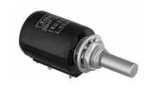
Rotary potentiometers are typically single or multi turn position sensors: they are actually potentiometer, built to be robust and more resistant to continuous movements and rotations. The output consists of an analog signal proportional to the shaft angle.
Optical rotary encoders
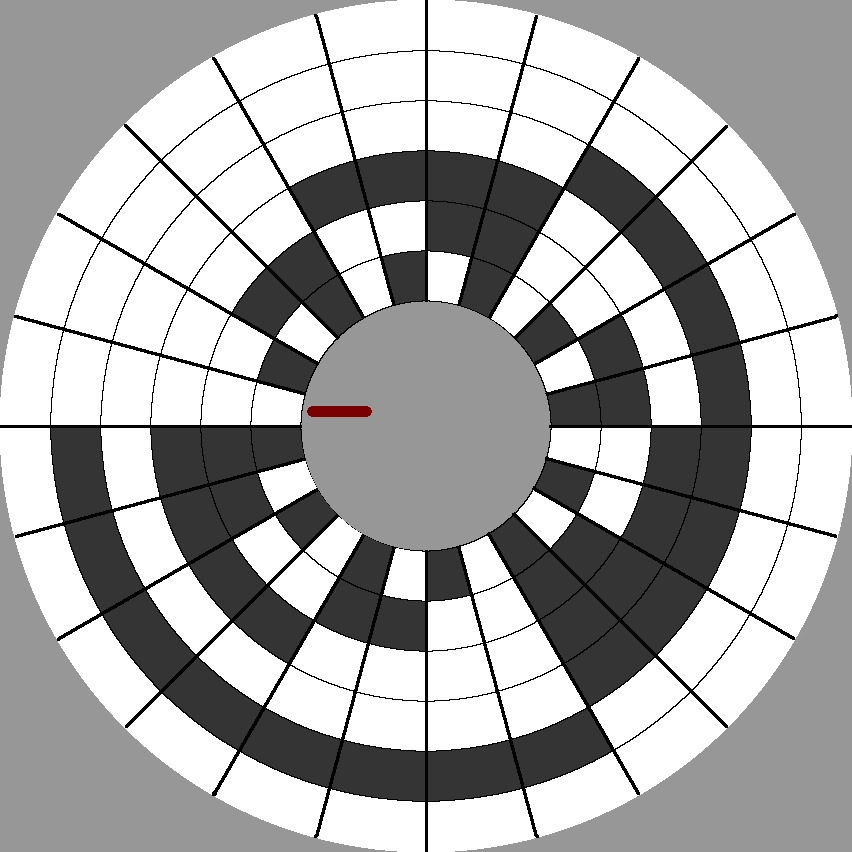
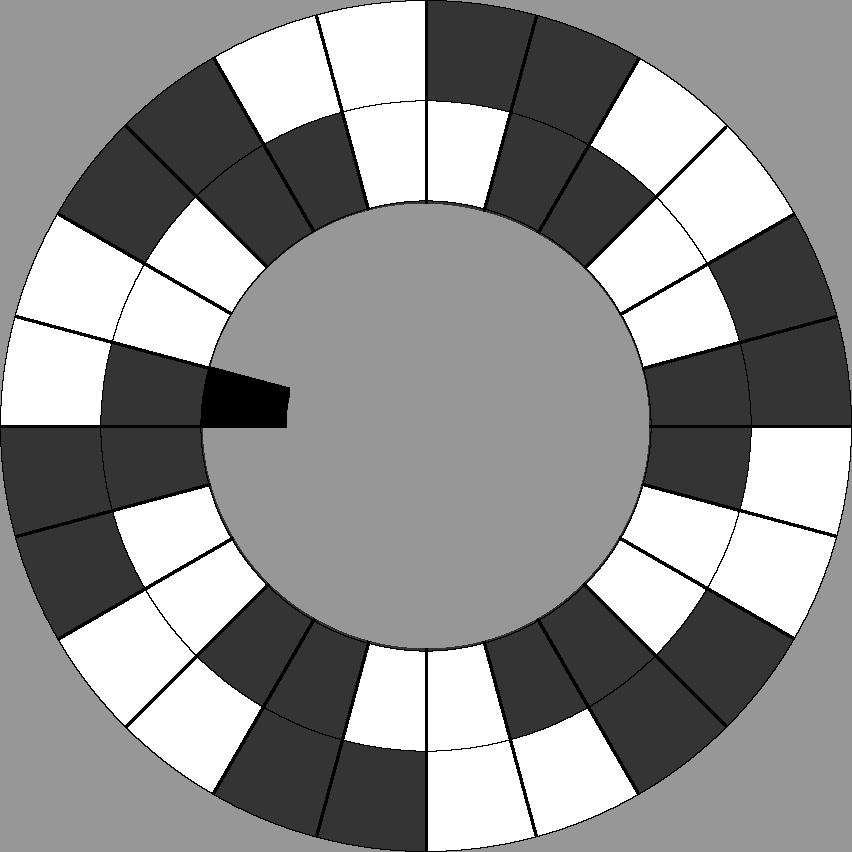
An optical rotary encoder is typically an n-bit object whose complexity increases exponentially with the required precision: the smallest the angle you want to be sensible to, the highest the number of bits, the highest the mechanical complexity of the sensor. This means that also the cost and the uncertainty associated to the output angle increase when you want a very precise sensor.
Optical sensors are made of a disc where black and white traces are drawn; a set of phototransistor or photoresistor (one for each colored annulus) reads back the content of the cell positioned on it (reflectivity coefficient is high for white cells and low - near zero - for black cells): as you can see from the image aside, the more the number of cells along the annulus, the higher the sensitivity, with obvious consequencies on uncertainty.
Resolvers
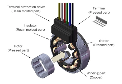
This type of sensor is quite complex, and the interface required to get the angle must be accurately designed. For this reason, typically, resolvers need an ASIC or a complex peripheral from advanced microcontrollers to calculate the angle position from an amplitude-modulated signal.
Resolvers are good and reliable sensors since they are mechanically robust and electrically immune to noise, however they are very sensitive to their mounting with respect to the shaft: resolver rotors (attached to the rotating machine shaft) must be centered and properly aligned to the resolver stator to reduce errors and offsets in angle conversion, so, this turns in a strong requirement toward mechanical designers that must pay a lot of attention to these aspects.
Moreover, the circuit used to converter resolver signals into an angle information introduces phase shifts and signal distortions, which could lead to a wrong angle conversion.
Comparisons
Relative position sensors
| Sensor | Pros | Cons |
|---|---|---|
| Mechanical | + Simple to realise + Simple electronics and algorithm |
- Mechanically weak - Low accuracy and precision - High sensitivity to vibrations - Reduced lifespan |
| Optical | + Simple to realise + Simple electronics and algorithm + Well-known, used in many application |
- Difficult to have high sensitivity (high number of colored cell on the disc) |
| Inductive | + Simple to realise + Simple electronics and algorithm + Well-known, used in many applications, + Reliable also in harsh, noisy, dusty and dirty environments + Very long lifespan |
- Sensitive to electromagnetic noise |
Absolute position sensors
| Sensor | Pros | Cons |
|---|---|---|
| Resistive | + Simple to realise + Simple electronics and algorithm |
- Mechanically weak - Low accuracy and precision - High sensitivity to vibrations - Reduced lifespan - Typically limited in number of turns |
| Optical | + Simple to realise + Simple electronics and algorithm + Well-known, used in many application |
- Difficult to have high sensitivity (high number of colored cell on the disc which means high number of bits) |
| Resolver | + Accurate and precise output + Reliable sensor + Increased lifespan + Not sensible to dust, acoustic and electromagneti noise + Low dependency on driving mode (input signal amplitude, output signals amplitude, input frequency) |
- Very complex electronic design and algorithm - High sensitivity to mounting (centering and alignment) - High cost (sensor+electronics) |
Share this page


Comments
Be polite and respectful in the comments section. In case of doubts, read this before posting.
Posted comments ⮧
Comment section still empty.
INDEX
INFO
STATISTICS
CONTACTS
SHARE