
About Touchstone file format
Brief compendium about Touchstone files
History
Touchstone files have been developed by EEsof before being acquired from HP. These ASCII files express in a very simple way the frequency behaviour of an n-port network; in every line, you can find the value (magnitude, phase, real, imaginary, depending on the chosen format) of each S-parameter at a defined frequency. The frequency points are listed in ascending order.
This format has become the de-facto standard for many tools and software used in RF, EMC compliance, design and verification, and simulation. For some simulation software, Touchstone files are used to represent Y and Z parameters, too.
Format
The Touchstone format contains four types of data: comments, option lines, data lines and noise data lines. Let's see how they are defined and
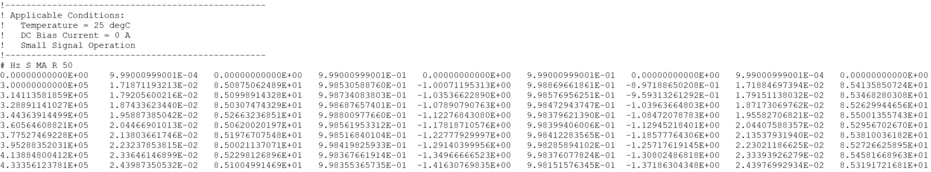
Comments
Comments are lines preceded by the symbol '!'. A comment can be added at the end of a data line, adding a ! at its beginning. There is no symbol for multi-line comments.
0
1
! This is a comment
data data data data data data data    ! This is a comment at the end of a data line
Option line
The option line is used to provide the format of the data in the next sections. The option lines start with the symbol '#' and have the following format
0
# <frequency unit> <type> <format> <Rn>
The possible values for each field are
0
# [Hz, kHz, MHz, GHz] [S, Y, Z, G, H] [MA, DB, RI] [Rn]
- frequency unit Unit of the datum in the frequency column
- type Type of datum (scattering matrix, impedance, admittance)
- format DB: dB/angle, MA: magnitude/angle, RI: real/imaginary
- Rn Reference resistance to whom the S parameters are normalized to. It is expressed in Ohm
Data
Data is formatted in the following way for a 2-port network.
0
1
<frequency1> |S11| <S11 |S12| <S12 |S21| <S21 |S22| <S22
<frequency2> |S11| <S11 |S12| <S12 |S21| <S21 |S22| <S22
If the network has n-ports, the Touchstone file becomes like this
0
1
2
3
4
5
6
7
8
9
10
<frequency1> |S11| <S11 |S12| <S12 |S13| <S13 |S14| <S14 ... |S1n| <S1n
             |S21| <S21 |S22| <S22 |S23| <S23 |S24| <S24 ... |S2n| <S2n
             |S31| <S31 |S32| <S32 |S33| <S33 |S34| <S34 ... |S3n| <S3n
             ...
             |Sn1| <Sn1 |Sn2| <Sn2 |Sn3| <Sn3 |Sn4| <Sn4 ... |Snn| <Snn

<frequency2> |S11| <S11 |S12| <S12 |S13| <S13 |S14| <S14 ... |S1n| <S1n
             |S21| <S21 |S22| <S22 |S23| <S23 |S24| <S24 ... |S2n| <S2n
             |S31| <S31 |S32| <S32 |S33| <S33 |S34| <S34 ... |S3n| <S3n
             ...
             |Sn1| <Sn1 |Sn2| <Sn2 |Sn3| <Sn3 |Sn4| <Sn4 ... |Snn| <Snn
Noise parameters
Noise parameters can be included in a Touchstone file too. typically, they are appended to the end of the file. The format used for each line (one line is one frequency point) is the following one:
0
<freq> <nf [dB]> <|Gamma|> <<Gamma [°]> <Rn>
- frequency This is the frequency step
- nf [dB] Minimum noise figure expressed in dB
- |Gamma| Magnitude of the source gamma (reflection coefficient) at the minimum noise figure
- <Gamma [°] Phase of the source gamma (reflection coefficient) at the minimum noise figure
- Rn Effective noise resistance normalized to the system impedance defined in the option line
Remember that the noise figure is defined as $$nf = 10 log_{10} \left( \frac{SNR_i}{SNR_o} \right) = SNR_{i,dB} - SNR_{o,dB} $$
Share this page


Comments
Be polite and respectful in the comments section. In case of doubts, read this before posting.
Posted comments ⮧
Comment section still empty.
INDEX
INFO
STATISTICS
CONTACTS
SHARE