
Inverters output power
3-phase 2-levels inverter model and power calculations
3-phase 2-levels inverter
A 3-phase 2-levels inverter is an electronic converter designed to transform DC electrical quantities in alternate voltage and currents, in which input voltage is modulated to get the desired output alternating voltage. Modulation is obtained switching between the bus voltage and the ground and the ouput voltage is the average value of this square wave.
These converters are typically used to drive motors, which contain reactive elements: this feature of the load must be considered during the design of an inverter to correctly size all the power components. Highly reactive components lead to high reactive power that an inverter must manage properly.
Before going into the details of calculations, it is good to have a reference schematics of a generic 3-phase 2-levels inverter.
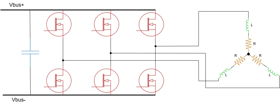
Please, note that this page is focused on 3-phase 2-levels inverters only. It is possible to realise power inverters with more phases and more than 2 levels.
Neutral point
Let's find the average voltage of the neutral point af an inverter.
The central point of the motor is known as 'neutral point'. In case of balanced (all impedances along the three branches are equal) and symmetric (the phase shift is constant between the three phases) load, its average voltage value over time is 0V with respect to the ground of the inverter, helping us in finding voltage, current and power formulas. The neutral voltage can be easily calculated using the Millmann's theorem: $$ v_N(t) = \frac{ \frac{v_{PHU}}{Z_U} + \frac{v_{PHV}}{Z_V} + \frac{v_{PHW}}{Z_W} }{ \frac{1}{Z_U} + \frac{1}{Z_V} + \frac{1}{Z_W}} $$ Since the load is balanced and symmetric, the three impedances are all equal to Z, then $$ v_N(t) = \frac{v_{PHU} + v_{PHV} + v_{PHW}}{3} $$ Now, let's explicit the expressions for each phase voltage $$ v_N(t) = \frac{1}{3} \left( V_{PH,PK}cos(2 \pi f t) + V_{PH,PK}cos \left( 2 \pi f t + \frac{2}{3}\pi \right) + V_{PH,PK}cos \left( 2 \pi f t - \frac{2}{3}\pi \right) \right) $$ Using prosthaphaeresis one gets $$ v_N(t) = \frac{1}{3} \left( V_{PH,PK}cos(2 \pi f t) + 2V_{PH,PK}cos(2 \pi f t) cos \left( \frac{2}{3}\pi \right) \right)$$ $$ v_N(t) = \frac{1}{3} \left( V_{PH,PK}cos(2 \pi f t) + 2V_{PH,PK}cos(2 \pi f t)(-\frac{1}{2}) \right) = 0$$
The phase voltage of the inverter corresponds to the phase-to-neutral voltage of the motor, even if neutral point and inverter ground are not galvanically connected!
However, this is not properly true in common 3-phase, two-levels switched inverters: since motor phase voltage is modulated through PWM between 0V and VDC, the neutral point moves at 0V, 1/3VDC, 2/3VDC, VDC periodically but keeping an average value of 1/2VDC. In this case, without considering the switching part and linearizing everything, we get the averaged formula for the neutral point voltage $$ v_N(t) = \frac{1}{3} \left( \frac{3}{2}V_{DC} + V_{PH,PK}cos(2 \pi f t) + V_{PH,PK}cos \left( 2 \pi f t + \frac{2}{3}\pi \right) + V_{PH,PK}cos \left( 2 \pi f t - \frac{2}{3}\pi \right) \right) $$ This gives $$ v_N(t) = \frac{V_{DC}}{2}$$ Since both the inverter phase voltage and the neutral point are centered at 1/2VDC, this constant value is subtracted in next calculation, shifting the phase voltages to 0V.
Phase voltages and currents
To analyse power, we need to write some equations. First of all, the voltage generated by an inverter (phase potential with respect to inverter ground) is described by the following equations $$ \begin{cases} v_U(t) = V_{PH,PK}cos(2 \pi f t) \\ v_V(t) = V_{PH,PK}cos(2 \pi f t - \frac{2}{3}\pi) \\ v_W(t) = V_{PH,PK}cos(2 \pi f t + \frac{2}{3}\pi) \end{cases} $$ Currents are instead dependent on the load. In case of a balanced and symmetric load, they can be written as $$ \begin{cases} i_U(t) = I_{PH,PK}cos(2 \pi f t - \phi) \\ i_V(t) = I_{PH,PK}cos(2 \pi f t - \frac{2}{3}\pi - \phi) \\ i_W(t) = I_{PH,PK}cos(2 \pi f t + \frac{2}{3}\pi - \phi) \end{cases} $$ These are known as phase quantities.
Line voltages and currents
Sometimes, 3-phase systems use another way to write voltages and currents, referred to as line current and voltages. Line voltage equations are the following ones $$ \begin{cases} v_{WV}(t) = \sqrt{3}V_{PH,PK}cos(2 \pi f t) \\ v_{VU}(t) = \sqrt{3}V_{PH,PK}cos(2 \pi f t - \frac{2}{3}\pi) \\ v_{UW}(t) = \sqrt{3}V_{PH,PK}cos(2 \pi f t + \frac{2}{3}\pi) \end{cases} $$ This system of equations comes from the following calculations: two adiacent phases follow these voltage equations $$ \begin{cases} v_U(t) = V_{PH,PK}cos(2 \pi f t) \\ v_W(t) = V_{PH,PK}cos(2 \pi f t + \frac{2}{3}\pi) \end{cases} $$ The line-to-line voltage then is $$v_{UW}(t) = V_{PH,PK}cos(2 \pi f t) - V_{PH,PK}cos(2 \pi f t + \frac{2}{3}\pi) $$ Using prosthaphaeresis rules one gets $$ v_{UW}(t) = V_{PH,PK}\left( -2 sin \left(\frac{4 \pi f t +\frac{2}{3}\pi}{2} \right) sin \left(\frac{-\frac{2}{3}\pi}{2} \right) \right)$$ $$ v_{UW}(t) = V_{PH,PK} \sqrt{3} sin \left( 2 \pi f t +\frac{\pi}{3} \right)$$ The line-to-line voltage (absolute value) is more or less 1.732 times the phase voltage.
Power Calculations
Instantaneous power is defined as $$ p(t) = v(t) \cdot i(t) $$ In a balanced and symmetric 3-phase system, the analysis can be reduced to a single phase $$ p(t) = v(t) \cdot i(t) = V_{PK}cos(2 \pi f t) \cdot I_{PH,PK}cos(2 \pi f t - \phi) $$ Where IPH,PK is the peak phase current generated by the inverter and VPK is the inverter peak output voltage. For a power inverter, the maximum current is limited by the technology and the maximum voltage by the modulation technique used. Developing the product of cosine we get $$ p(t) = \frac{V_{PK}I_{PH,PK}}{2} (cos(\phi) + cos(4 \pi f t - \phi)) $$ The first term represents the active output power of a single phase $$ P = \frac{V_{PK}I_{PH,PK}}{2} cos(\phi) $$ The total inverter output (active) power is $$ P = 3 \frac{V_{PK}I_{PH,PK}}{2} cos(\phi) $$
In AC systems, RMS values are preferred so we can rewrite the formula as $$ P = 3 \frac{V_{RMS}\sqrt{2} I_{PH,RMS}\sqrt{2} }{2} cos(\phi) = 3 V_{RMS} I_{PH,RMS} cos(\phi) $$ However, the maximum output voltage of a 3-phase inverter is dependent from the DC bus voltage and the used modulation technique. For a simple SPWM modulation, the maximum voltage is $$ V_{PK} = \frac{V_{DC}}{2} $$ The output active power becomes $$ P = 3 \frac{V_{DC}I_{PH,RMS}}{2\sqrt{2}} cos(\phi) = 3 \frac{V_{DC}I_{PH,PK}}{4} cos(\phi) \quad [W] $$ The output reactive power is $$ Q = 3 \frac{V_{DC}I_{PH,RMS}}{2\sqrt{2}} sin(\phi) = 3 \frac{V_{DC}I_{PH,PK}}{4} sin(\phi) \quad [VAR] $$ And the output apparent power is $$ S = 3 \frac{V_{DC}I_{PH,RMS}}{2\sqrt{2}} = 3 \frac{V_{DC}I_{PH,PK}}{4} \quad [VA] $$
Output power
As already mentioned, the total output power depends on the maximum voltage an inverter can provide and this is related to the chosen modulation technique.
SPWM
In case of a very simple sinusoidal modulation, the maximum power transferable to the motor is proportional to the modulation index $$P = 3 \frac{V_{DC}mI_{PH,RMS}}{2\sqrt{2}} cos(\phi) = 3 \frac{V_{DC}I_{PH,PK}}{4} cos(\phi) \quad [W]$$
Share this page


Comments
Be polite and respectful in the comments section. In case of doubts, read this before posting.
Posted comments ⮧
Comment section still empty.
INDEX
INFO
STATISTICS
CONTACTS
SHARE