
What is a bridge
A bridge is an electrical circuit used to provide a defined amount of current (sometimes at a precise output voltage) to a generic load: this topology is very common in electronics and for this reason, it deserves a deep analysis.

The load can be a simple resistor or, more often, an inductive load; keep in mind that for motors, solenoids, valves, or pumps, their actual resistance and inductance values change accordingly to the working ambient temperature, mechanical deformation, non-ideal saturation effects, reluctance variations and so on. These effects must be accounted for during the design to get a robust system. In other cases the load can be a transformer, with a regulated voltage on the isolated side (e.g. isolated full bridge DCDC, push-pull DCDC, LLC converter).
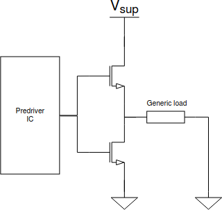
The pre-driver shown in the pictures is a gate driver circuit (usually an IC with high side and low side driving capabilities), which allows driving properly the command terminal of a switch: depending on the application, the switch can be a simple MOSFET, an IGBT or a SiCMOS; the pre-driver IC to be used changes a lot depending on the application requirements (bus voltage, switching frequency, power required, average current in the load, maximum acceptable losses, isolation and so on). When bus voltage is higher than, typically, 60V, pre-driver ICs usually consist of isolated gate drivers with internal galvanic isolation between the low voltage and the high voltage domain. In many cases, especially in the automotive field, gate drivers have internal diagnostic features, allowing to know the state of the switch and to perform additional monitoring on the system; in these components, the bidirectional communication between the two isolated domains is ensured by a capacitive or inductive coupling which, in some cases, allow to reach very high data exchange rates. On the other hand, the drive of the power device command terminal (gate, base) is made possible through external small converters which supply the high voltage domain starting from the low voltage one.
The various bridge topologies derive from one configuration, the so-called 'elementary cell', which is made of two switches and an inductor; in the case of the bridge circuit, the inductor is part of the actual load to be driven rather than being a component used to store inductive energy; moreover, as you can see from the following image, the capacitors are not shown since they are placed at the input and the output of the cell to provide the required current during the OFF phase of the converter so their position changes accordingly to the configuration of the cell itself: it is possible to get a step-down, a step-up or a step-up/step-down chopper converter just by changing the input and the output port (and so the capacitors positions) of the same cell. The bridge is just an adaptation of the step-down version of the elementary cell in which the inductor is not part of the output LC filter but the load itself; moreover, the load has usually a non-negligible series resistance (which, on the contrary, should be as low as possible in a DCDC converter to reduce losses).

When the elementary cell is used to create a bridge, only the input capacitor is required; when, on the contrary, the output must not be a constant current but an amplified signal, the inductor becomes part of an output LC filter used to remove the high-frequency contribution of the switching node: in this case, we obtain a buck converter used as a class D amplifier where the switching frequency is very high (order of MHz) and the LC filter is dimensioned not to remove audible frequencies from the output signal but to attenuate as much as possible the square wave contribution... as you can see, all these commonly known applications are just different faces of the same circuits with only a few modifications!
Working principle
As said, the bridge topology is used when a defined current must be provided to a load. For the sake of simplicity, let's think of an electromechanical valve: they are often used to automatically open or close a pipe without the need for a knob, to modulate the flow rate in a fluid dynamic circuit (e.g. heaters, coolers, pump-based fluid dynamic circuits, chillers, industrial washing plants and so on) or to move fluid-based mechanical parts like plungers, hydraulic cylinders, generic linear actuators; the fluid can be water, mineral oil or other fluid solutions.
All these electromechanical components (modelled as resistor + inductor loads) require defined currents to provide forces to move a mechanical actuator. According to the required target, an average constant current tracking the desired setpoint must be provided: this can be done using shunt resistors in series with the load, read back by the control system. The driver, instead, is a set of PWM-commanded switches, supplied by the bus voltage which provides a switching voltage to the load, at a frequency which is mechanically filtered by the plant itself. The actual load current will exhibit a ripple which is a function of the load inductance and the switching frequency: it must be as low as possible and must not generate any 'trembling' of the actuator, especially when the switching frequency is low - it can happen that if the mechanical part of the solenoid driven system is too sensitive to higher frequencies, it could slightly move or tremble following the ripple current; another important point is to use switching frequency higher than 20kHz to make the system inaudible (not always required).

In a bridge-based system, there is always one high-side and one low-side switch, used respectively to provide the current to the load and to allow current recirculation. The picture shows how the current flows in the load.
When the high side switch is ON, the bus voltage is applied to the load and the current increases with a VL+/L slope. Instead, when the low side is ON, the current decreases with a VL-/L. It is important to note that Vload is different from VL+ and VL-: the inductive part of the load must see an average voltage which is 0V (integral of inductor voltage over the time must be 0V): to satisfy this condition we can say that the VL+=Vsup-Vload,avg and VL-=-Vload,avg. When the switching period is much lower than the RL tau then an average current steady state (proportional to the average voltage divided by the load resistance) with a controlled ripple can be reached.
Driving polarity
Independently from the bridge topology used, there are different driving polarities to get the same average constant current in the load. Each mode has its own merits and defects.
Low side driving
When one load terminal is tied to the supply voltage and the current is modulated through a switch tied to the ground, we talk about low-side driving. If the load is inductive a recirculating diode is required between the switching node and the supply voltage node to allow current recirculation when the switch is OFF. This is the simplest way to drive an inductive load: easy and low cost.
High side driving
This is the opposite of the low side driving. This driving mode is usually discouraged since additional charge pumps in the case of electron-based devices or negated logic in the case of hole-based devices need to be implemented. Moreover, hole-based devices are slower than electron-based devices and for this reason, they are not appropriate for high-frequency switching systems. Also in this case, a recirculating diode is required between the ground and the switching node to allow the energy stored in the inductor to discharge through the load itself.
Active recirculation driving
To better control the current in the load and to reduce losses, instead of using recirculating diodes, one can use two bidirectional active switches (like in the step-down version of the elementary cell). Additional control logic to prevent shoot-through and, eventually, to perform some diagnostics is required but this solution gives many advantages and is often used in many design cases. Note that, in case of high load currents, this driving mode does not help so much to reduce power dissipation since the recirculating current will pass in the body diode rather than through the switch channel (at high currents the voltage drop due to the switch ON resistance becomes higher than the body diode forward voltage). Moreover, only MOSFETs can be effectively used in this mode since they are bidirectional devices (BJT and IGBT are not), even if they are optimized to conduct current in a defined direction.
Driving modes
There are typically three driving modes for bridges which must be chosen according to the requirements.
Half bridge mode
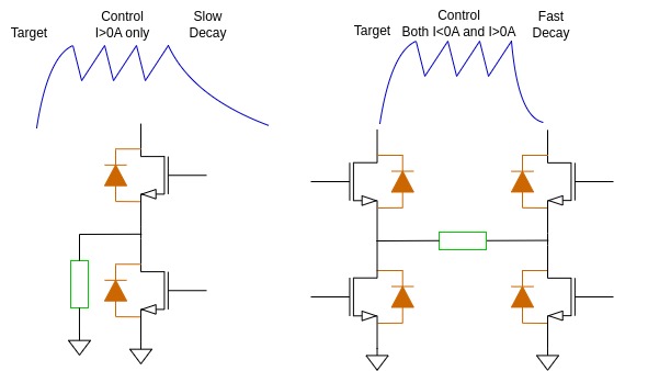
This mode requires just one half-bridge. It must be chosen when the load current will always have one direction only and there will be no need to control the current decay when turning off the driving circuit.
Full bridge mode
Full bridge becomes necessary when the current can flow in both directions and when it is required to control both rising (from 0A to the target value) and falling times (from the target value to 0A) of the load current.
Mixed mode
This mode requires a full bridge hardware design but the control system will use it in both half and full bridge, according to the target current and the current profile required. Fullbridge mode is fundamental for EMI and power loss reduction so it should be used whenever possible.
Share this page


Comments
Be polite and respectful in the comments section. In case of doubts, read this before posting.