➔ Index of ⦁ Introduction to Electronic Devices ⦁
Electronic Devices - Part I: Introduction
Electronics is mainly based on semiconductor devices, which rely on solid state physics theories. Here you can find an introduction to this vast topic.
Electronic devices
An electronic device is a device in which electrons and holes have a complex interaction, more complex if compared to passive components. The theory behind modern electronic devices is based on quantum mechanics and solid-state physics and for this reason, some counterintuitive concepts will be encountered during the presentation of this topic. Electronic devices are mainly used as switches and amplifiers: all electronic circuits are made of electronic components which act in these two ways! Just remember that an amplifier can be used not only to amplify but also to attenuate a signal, to sum and subtract two signals, to combine them in a complex way, to generate periodic signals and so on.
In this first introductory article you will find some concepts that will be clarified in the next pages, just take them as they are, even if they seem not so clear!
Before modern electronic devices
Before we could have semiconductor-based electronic devices, we used to have valves (called also vacuum tubes): they were invented as a result of some experiments on hot filaments to be used for lighting purposes. Edison himself, while trying to understand the reasons behind the breakage of the filament in bulbs, observed a small current through a galvanometer when a positively charged plate was put in front of the bulb itself; he couldn't explain the phenomenon but today we can easily say that electrons were emitted through thermionic emission by the incandescent filament and they were attracted toward a positive potential thanks to the applied external electric field.
The first devices were all based on thermionic emission: first diodes were bulbs able to carry electrons in one direction only. Next, triodes were developed: an additional driving electrode was added; such pole was internally connected to a grid and used to modulate the amount of electrons flowing from cathode to anode (called 'plate'). As you can imagine, the first use for triodes was amplifiers for audio and radiofrequency applications. And yes, some incandescent bulb filaments release electrons because of their high temperature even if most of them (at least commercial ones) emit light when an electron goes back to a lower energy state, without any electron emission.
Diode
The vacuum tube diode was made of a metallic filament inside a vacuum tube which could reach high temperatures with no breakage - exactly like a modern incandescent bulb. On the opposite side of the tube, always inside the bulb itself and in front of the filament, there was a metallic plate used to polarize the diode. The device needed a certain amount of current to heat the filament so that it could start to release electrons thanks to thermionic emission: the required energy had to be equal or higher than the work function of the metal used to build the filament and, for this reason, these devices used to require a huge power to work and to waste a high percentage of it: heat dissipation was one of the main problems the designers were concerned about - first objects containing such devices were like wood burning stoves in size and dissipated power! But now we need to explain what is meant by 'work function': the work function is the minimum energy needed to allow an electron to 'fly away' from the bulk material and not to go back. It is defined as the difference between the energy of an electron very close to the surface of a bulk solid substance and the same electron in the material itself, close to the Fermi level (the electrochemical potential at the equilibrium inside the material). $$W=e^-\phi - E_F$$ where e- is the electron charge, ϕ is the potential at the surface of the material, e-ϕ is the energy of the electron at the surface of the material and EF if the Fermi level; each extracted electron requires a W amount of energy for a defined material. Some work function values for common metals are given in the table below.
| Element | Work function [eV] |
|---|---|
| Silver (Monocrystal 100) | 4.64 |
| Gold (Monocrystal 100) | 4.20 |
| Carbon (Polycrystal) | 5.0 |
| Copper (Monocrystal 100) | 5.10 |
| Iron (Monocrystal 100) | 4.67 |
| Germanium (Polycrystal) | 5.0 |
| Sodium (Polycrystal) | 2.36 |
| Platinum (Polycrystal) | 5.64 |
| Silicon (n-doped) | 4.85 |
| Wolfram (Polycrystal) | 4.55 |
As you can imagine, the work function changes with the crystalline structure of the solid (monocrystalline, polycrystalline, amorphous) and, if the substance is anisotropic, it may vary with the surface used to perform the measurement. Another aspect that can influence the measurement of the work function is the rugosity of the used specimen under test but, if the surface is clean and smooth enough, this parameter can be neglected.
The current density generated through thermionic emission, instead, follows the Richardson's equation: $$J=\frac{4\pi m_e e^- k^2}{h^3}\lambda_m T^2e^{\frac{-W}{kT}} \quad \left[\frac{A}{m^2}\right]$$ where λm is a material-dependent correction factor, T is the temperature, k is the Boltzmann constant, h is the Planck constant, me is the electron mass and W is the work function.
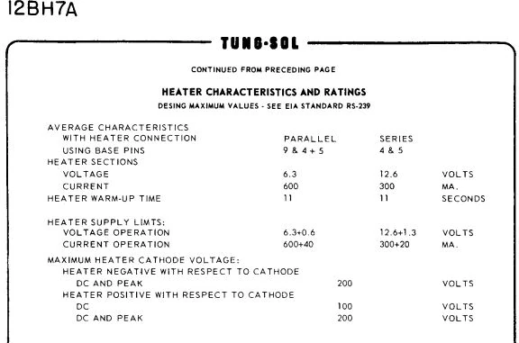
Now, let's say we want to build a circuit where a diode lets 1A flow; the following amount of power is needed only for the filament! $$1A = \frac{1C}{1s}$$ $$e^- = 1.602177e^{-19}C \rightarrow 1C = 6.241508e^{+18}e^- \rightarrow 1A = \frac{6.241508e^{+18}e^-}{1s}$$ Let's assume that the filament is made of amorphous wolfram, so $$P_{tot} = \frac{4.55eV*6.241508e^{+18}e^-}{1s} \approx 4.55W$$ remembering that $$1eV = 1.602e^{-19}J$$ Now let's look at a double triode datasheet and focus only on the heater data: dissipated power is similar to the calculated one (it requires 6.3V x 0.6A for the heater to work). Note that the voltage applied to the heater can be both DC or AC (specified as RMS value). This is because many of these components were designed to be connected to an AC voltage line, eventually generated through an appropriate transformer.
Triode
The functioning of a triode can be explained in a few key steps:
Electron Emission
The triode contains a cathode, which is heated to a high temperature. This heating process causes the cathode to emit electrons through thermionic emission.
Electron Flow
The emitted electrons are attracted to the positively charged anode (also known as the plate). This creates a flow of electrons from the cathode towards the anode, known as electron current.
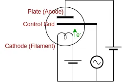
Control Grid
Positioned between the cathode and the anode is the control grid, typically made of a fine wire mesh. The control grid is usually maintained at a negative voltage with respect to the cathode. This negative voltage repels some of the electrons emitted by the cathode, controlling the flow of electrons between the cathode and the anode.
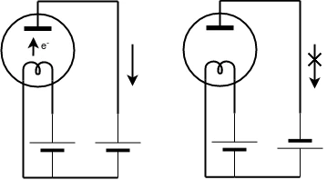
Grid Voltage Modulation
By varying the voltage applied to the control grid, the flow of electrons between the cathode and the anode can be modulated. When the grid voltage is more negative, it repels more electrons, reducing the electron current flowing towards the anode. Conversely, when the grid voltage is less negative (or even positive), it lets more electrons flow towards the anode, increasing the electron current.
Amplification
The ability to control the flow of electrons between the cathode and the anode through the grid voltage modulation allows the triode to function as an amplifier. Small variations in the voltage applied to the control grid result in proportionally larger variations in the electron current flowing between the cathode and the anode. This property enables the triode to amplify weak electrical signals.
Overall, the triode's operation relies on the control of electron flow through the control grid, allowing it to function as an amplifier or a switch in electronic circuits. As you can see, this can be seen as the predecessor of the transistor, bigger, less reliable, hotter, heavier and much less efficient ;)
Share this page


Comments
Be polite and respectful in the comments section. In case of doubts, read this before posting.
Posted comments ⮧
Comment section still empty.
INDEX
INFO
STATISTICS
NEXT ARTICLE
CONTACTS
SHARE