➔ Index of ⦁ Introduction to Electromagnetic Compatibility ⦁
Introduction to EMC: LISNs
What is a LISN and why it is mandatory even in the most basic EMC laboratory
EMC testing and the need for a LISN
Before talking about the technical details behind LISNs, we need to understand why they are needed in all EMC setups.
LISNs (Line Impedance Stabilization Networks) are simple circuits used to decouple the output impedance of a source from the input impedance of our circuit, making the equipment under test independent of the nature of the used power supply. Since, for EMC qualification and homologation tests, we have to perform some measurements on the noise generated by our equipment, we have to ensure that the setup introduces small variability so that tests can be repeated with similar results also in different setups; in this way, our EUT sees the output impedance of the LISN (which is more or less always the same) rather than the variable output impedance of a power supply - in case of power supply lines - or the impedance of another type of interface - in case of a signal line.
All LISNs provide a port for noise measurement, to be connected to a receiver through coaxial cable or similar.

LISN can be used for both low and high-voltage systems, so be sure to choose the proper one when starting your EMC tests: it is important to use the right LISN with appropriate voltage/current ratings, also for safety reasons. A LISN for a 24V/1A low voltage apparatus will be completely different from the LISN needed for a 400V/300Arms battery-supplied inverter!
Typical LISN characteristics
Automotive LISN
Automotive LISN is thought to simulate the effect of cables 5m long (typical cable length in a car). They are made of a series inductance of 5uH, an input capacitance of 1uF and an output capacitance of 100nF (in series with 1kOhm to be used as measuring resistance). Their output impedance is shown below (obtained with a short circuit on the power supply side).
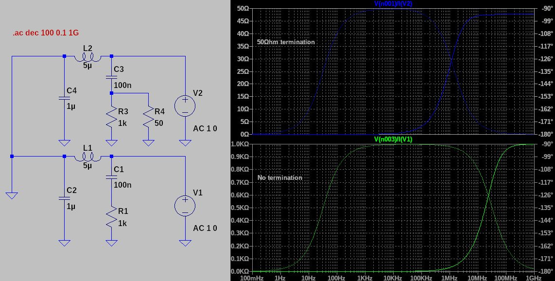
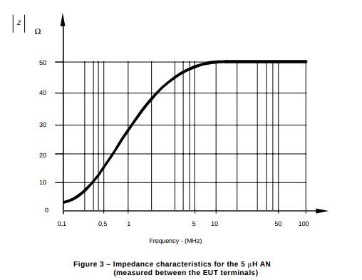
The impedance of the network goes from 0Ohm to 1kOhm at high frequencies. If you account for the 50Ohm termination, you'll get a high-frequency impedance slightly lower than 50Ohm due to the parallel with 1kOhm. Note that with the termination inserted, the frequency response is different: the pole frequency lowers. The LISN output impedance is the following: $$Z(s) = \frac{sL(\frac{1}{sC}+R)}{sL+\frac{1}{sC}+R} = \frac{sL(1+sCR)}{s^2 LC + sCR + 1}$$ There are two zeroes and two complex conjugate poles (the first result is without 50Ohm termination impedance). $$f_{z1} = 0Hz$$ $$f_{z2} = \frac{1}{2\pi RC} = 1.592kHz \quad or \quad 33.421kHz$$ $$f_{p1,p2} = \frac{-RC \pm \sqrt{C^2R^2 - 4LC}}{2\pi 2LC} = -1.592kHz, -31.829396MHz \quad or \quad -34.194kHz, -1.481567MHz $$ When measuring a multi-LISN setup, all unused LISNs must be terminated with 50Ohm! Moreover, all these LISNs allow us to perform measurements, typically, in the 10kHz-300MHz range; outside of this range, results are not reliable anymore.
EMI receiver: a quick overview
The measurement is done through an EMI receiver (whose circuit is similar to the one inside a superheterodyne-based radio), and then data is digitally processed for the user.
Today, FFT EMI receivers are allowed too since they have a reduced scan time; they are widely accepted by most EMC-related measurement standards with some adjustments on the setup and noise limits. LISN output port is connected to the receiver through a 50Ohm coaxial cable and the EMI receiver will measure the amount of noise generated by our equipment on the 1kOhm shunt resistor in the form of voltage variations. The result may vary a lot according to the selected detector circuit:
- peak detector: it is used for detecting the maximum of the signal in time domain, then windowed at a sliding frequency and converted into the frequency domain; in this way we can see the noise maximum modulus for each frequency
- quasi-peak detector: it is typically made of a circuit having a very low charging time and a very high discharging time, in the order of tens/hundreds of ms; quasi-peak detector, if properly set, can be used to understand how often a certain disturbance happens in our equipment under test when compared to the peak detector output: you have to set the right measurement time to get a reliable measurement
- average detector: it performs the average on the output LISN signal to provide its mean noise level; similar to the quasi-peak detector, you have to properly set the measurement time
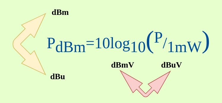
The output of the EMI receiver is then amplified, sampled and converted to make it available to the user through a PC or a screen; it is typically expressed in dBuV rather than uV since the variability of the noise level is very high: a logarithmic conversion to dB is preferred; the frequency axis is plot in a log scale too, as the frequency span is typically very high. The noise level is expressed in dBuV, which is defined as follows: $$dB_{\mu V} = 20log_{10}(\frac{V_{meas} [\mu V]}{1\mu V})$$
Consumer electronics LISN
Consumer electronics is typically connected to mains, so, for this reason, we have to consider longer wiring harnesses (from the general building mains to the apartment socket), up to 50m. This LISN is made of a 50uH series inductance, an input capacitance of 1uF and an output capacitance of 100nF (in series with 1kOhm to be used as measuring resistance). In some cases a 250uH prefilter is required.
Share this page


Comments
Be polite and respectful in the comments section. In case of doubts, read this before posting.
Posted comments ⮧
Comment section still empty.
INDEX
INFO
STATISTICS
PREVIOUS ARTICLE
NEXT ARTICLE
CONTACTS
SHARE