
Capacitors Q factor
What is the Q factor of a capacitor and why it should be considered during early design stages
Q factor definition
Q factor (quality factor) of a capacitor is defined as the ratio between the reactance and the resistance of the capacitor itself. $$Q = \lvert \frac{X}{ESR} \rvert = \lvert \frac{1}{\omega C ESR} \rvert = \lvert \frac{1}{tan \delta} \rvert$$

Panasonic EEHZK1E151XP
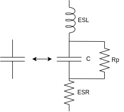
It is a good way to determine the efficiency of a capacitor (at a defined frequency and temperature) and, eventually, its behaviour in tunable circuits where a good selectivity over frequency is desired. Note that the quality factor is the inverse of the dissipation factor, explained below. Both factors consider only C and ESR values, without accounting for parallel resistance and ESL: the first one is used to model leakage across the dielectric and is a resistor in the order of hundreds of kOhm to GOhm. ESL instead is useful to understand if the capacitor introduces parasitic inductance which could be harmful to our circuit - both high-frequency designs and power converters are heavily affected by this parameter; typically the higher the worse.
Dissipation factor

and tand
representation
Q factor helps to understand if the selected capacitor is suitable for the application, giving an initial hint on how much power it will dissipate, considering the ripple across it. It is commonly used in power converters and the higher it is the better it is.
Let's consider an AC circuit in which a capacitor is driven by an ideal and purely sinusoidal voltage generator. Then the dissipation factor is defined as $$DF = \frac{i^2 ESR}{i^2 X} = \lvert tan \delta \rvert = \omega C ESR$$
tand is the ratio, in the phasors domain, between the resistance and the reactance of an RC dipole and delta is the angle between the imaginary - reactance - axis and the phasor of the dipole.
Dissipation factor is useful when you want to compare two different capacitors (pay attention to the testing condition reported in the datasheet). Typical values for ESR for different types of capacitors are shown below; you can expect higher DF - which means higher ESR - for older technologies capacitors.
| Capacitor type | Typ ESR [Ohm] |
|---|---|
| Standard Aluminum | 0.1-50 |
| Low-ESR Aluminum | 0.1-10 |
| Standard Tantalum | 0.5-5 |
| Low-ESR Tantalum | 0.05-1 |
| Ceramic | 0.001-0.1 |
ESR vs temperature
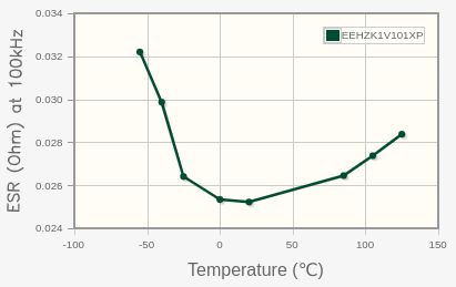
Dissipation factor (and, alternatively, quality factor) sensibly changes with temperature and frequency. As you can imagine, the higher the temperature, the higher the DF since resistive elements inside the capacitor increase with temperature. Here on the side, you can find a typical curve for Panasonic-EEHZK1E151XP, a Low-ESR (Hybrid Polymer-Aluminum SMD), 150uF, 25V, Automotive rated, -55 to 125°C temperature range capacitor.
In this specific case you can note that at low temperatures ESR is pretty high: this happens because in aluminium capacitors the electrolyte conductivity increases with temperature, so, we have mainly two contributors to ESR. At low temperatures electrolyte conductivity is still low (and it increases with temperature); at higher temperatures, ESR is dominated by resistive elements from the electrolyte to the external component leads. This phenomenon is exacerbated in standard aluminium capacitors; in this case, instead, it is mitigated since the capacitor is a hybrid one.
ESR vs frequency
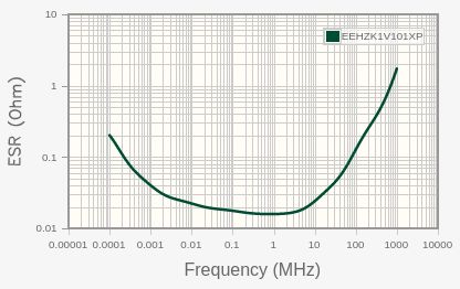
Note that ESR changes a lot with frequency! When you perform preliminary calculations on your selected capacitor, please look at the testing conditions since in many cases ESR vs temperature graph is given for a capacitor working at a different frequency from the one you are interested in. Sometimes manufacturers provide the maximum RMS current in the capacitor at a given temperature and frequency, then specify a factor for various frequency ranges (the lower the frequency, the lower the maximum RMS current allowed).
Tand vs temperature
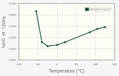
Also in this case the graph is related to Panasonic-EEHZK1E151XP capacitor, As you can see the profile of this curve is very similar to the ESR-vs-temperature one. Small differences are caused by the capacitance change over temperature: typically these types of capacitors have lower capacitances at low temperatures so looking at tand parameter is good since it also accounts for these variations.
Share this page


Comments
Be polite and respectful in the comments section. In case of doubts, read this before posting.
Posted comments ⮧
Comment section still empty.
INDEX
INFO
STATISTICS
CONTACTS
SHARE