➔ Index of ⦁ Introduction to Digital Electronics ⦁
Introduction to digital electronics
Brief introduction to digital electronics and basic digital operations
What is digital electronics
Digital electronics is a vast electronics branch mainly focused on data storage, transmission and manipulation through circuits capable of reproducing complex operations in a binary form. It differs from analogue electronics since operations are performed on, let's say, 'static', well-defined and quantized signals rather than on continuous, time-varying and eventually noisy signals. Nowadays, digital electronics is used too to replace analogic circuits to reduce power dissipation and, when possible, to improve performance: for example, we can think of audio applications (stream converters, operations on audio signals, file storage, signal amplification, signal transmission and so on) that have been one of the first fields where analogue electronics has been used but these circuits have been mostly replaced by their digital counterparts since they are simpler and smaller.
Digital electronics became possible through the development of semiconductor-based switches and a continuous process of integration. Everything in digital electronics is made of switching transistors, more and more integrated in small areas, performing operations at very high speeds.
Basic digital operations
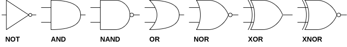
Digital operations are always made on binary values, where the logic 1 is typically represented by a voltage greater than 0V and a logic 0 by a voltage equal to 0V. The basic digital operations are NOT, AND, NAND, OR, NOR, XOR, and XNOR, and they can be implemented with a few transistors in small elementary cells. When analyzing a digital circuit you will see a lot of symbols which represent one of the cited operations; in the following image, you can see the symbol associated with its operation. The block of transistor yjat performs a logical operation is generally called 'gate', so, in the next paragraphs, we will talk of 'NOT gate', 'AND gate', 'XOR gate' and so on.
NOT gate
NOT gate inverts the logical value of a signal (from 0 to 1 and vice versa); this gate has just one operand. This is the simplest binary operation and the gate can be realized with just two transistors (if CMOS/BJT-based technology is used) or with one transistor and one resistor (in case Resistor-Transistor logic is used). $$\begin{array} {} In & Out = \overline{In} \\ 0 & 1 \\ 1 & 0 \end{array}$$
AND gate
AND gate combines two operands and returns a logic 1 only if the two inputs are logic 1. $$\begin{array} {} In1 & In2 & Out = In1 \cdot In2 \\ 0 & 0 & 0 \\ 0 & 1 & 0 \\ 1 & 0 & 0 \\ 1 & 1 & 1 \end{array}$$
NAND gate
NAND gate is, basically, an AND gate with a NOT after it, so, it will return 0 only if both input operands are 1. $$\begin{array} {} In1 & In2 & Out = \overline{In1 \cdot In2} \\ 0 & 0 & 1 \\ 0 & 1 & 1 \\ 1 & 0 & 1 \\ 1 & 1 & 0 \end{array}$$
OR gate
OR gate returns 0 only if both the input operands are 0. It returns 1 in the other cases. This is also called 'inclusive OR', which stands for the first OR the second OR both of them. $$\begin{array} {} In1 & In2 & Out = In1 + In2 \\ 0 & 0 & 0 \\ 0 & 1 & 1 \\ 1 & 0 & 1 \\ 1 & 1 & 1 \end{array}$$
NOR gate
NOR gate, as for the NAND gate, is an OR gate with a NOT after it: it returns 1 only when both inputs are 0. $$\begin{array} {} In1 & In2 & Out = \overline{In1 + In2} \\ 0 & 0 & 1 \\ 0 & 1 & 0 \\ 1 & 0 & 0 \\ 1 & 1 & 0 \end{array}$$
XOR gate
XOR gate is the binary version of the sum between two binary digits. It returns 0 when both operands are equal and 1 when different. This is also called 'exclusive OR' which means ONLY the first OR ONLY the second. $$\begin{array} {} In1 & In2 & Out = In1 \oplus In2\\ 0 & 0 & 0 \\ 0 & 1 & 1 \\ 1 & 0 & 1 \\ 1 & 1 & 0 \end{array}$$
XNOR gate
Again, the XNOR gate is an XOR gate with a NOT after it. $$\begin{array} {} In1 & In2 & Out = \overline{In1 \oplus In2} \\ 0 & 0 & 1 \\ 0 & 1 & 0 \\ 1 & 0 & 0 \\ 1 & 1 & 1 \end{array}$$
Conclusions
Now that you know how every single gate works, you can build your digital circuit using discrete components; I suggest starting with 74HC gates which are very simple to use (no particular drawback or leakage to account for when designing the circuit, good tolerance to environmental electrical noise, good propagation delay, rise and fall times).
In the next articles I'll describe some basic digital circuits everyone should know before starting a complex and detailed design.
Share this page


Comments
Be polite and respectful in the comments section. In case of doubts, read this before posting.
Posted comments ⮧
Comment section still empty.
INDEX
INFO
STATISTICS
NEXT ARTICLE
CONTACTS
SHARE