➔ Index of ⦁ Introduction to Digital Electronics ⦁
Digital circuits hardware design
Which are the main steps behind the design of a digital circuit? Let's analyse the steps, from the architectural definition to the physical design of the die, with focus on languages and file formats used in the VLSI industry.
Design levels

Unless you are designing a very basic, simple, stupid and slow digital circuit acting just like an up/down counter, you need some level of automation to speed up the design and to exchange data at various steps. Digital designs can be large and complex (remember VLSI - Very Large Scale of Integration - an acronym you will find a lot from now on) so we need an effective way to divide the tasks of the flow and to represent what we are designing in a universally recognized way, through visual or textual representations. In a few words, we can't do VLSI design drawing by hand the whole circuit, MOS by MOS on a piece of paper 1km2 wide; we need faster and more reliable methods and tools.
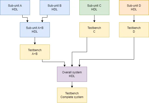
As you can see from the image on the side, digital design is divided into many steps and knowledge areas. The real-world digital designer doesn't see all of them but just a small part of the whole design process, and, typically, he becomes deeply specialized in behavioural, RTL and (partially) gate-level design.
Nowadays, circuit-level implementation is automatically performed by high-level synthesis tools and the digital designer doesn't have to worry about the type of gate or its physical and timing characteristics since he will not choose the technology during the synthesis: this is arranged by the tool and the physical library you work with. If there are more versions available of the same logic gate in your library, the most appropriate can always be chosen, typically at the end of the design, when the circuit performances must be improved and refined, by substituting one gate with a more suitable one. In any case, the digital designer doesn't have to design the gate, the memory cell, the flipflop nor the MOSFETs inside of it.
Physical level is finally done by the technology guy, the guru of doping, donors and acceptors density, switching power dissipation, parameters drift and ageing, static and dynamic power losses: they are not digital designers anymore but physicians, chemists, material scientists, experts of solid state physics and analogue designers. This is black magic! The only way you have to learn about the most advanced solutions in this field is by applying for a job in a big semiconductor company; all the remaining stuff you find on the internet about this topic is just the surface of this very complex matter.
Languages for IC design
An important remark before proceeding with a deeper description of the various IC design steps: all the modelling and description languages listed below are NOT to be intended as programming languages. You are NOT programming anything nor executing any code, you are DESIGNING a circuit using a specific textual representation that can describe the behaviour, the succession of operations, the structure and the shape.
Behavioral level
At this level, the system is described without considering the actual circuit implementation using high-level description languages. These are behavioural modelling languages; they do not enter the deepest details of the subcircuit, logic gate and CMOS cell, but describe "how" the circuit must work and which operations it should be capable of.
Nowadays, many synthesis tools can extract a working HDL description of the system from a behavioural representation and this helps a lot the designer to speed up the design process, especially if the system does not require a special optimization process and can rely on previously designed blocks.
Note that, sometimes, you can synthesize a circuit starting from the behavioural description; in other cases, when the language doesn't allow doing so, the behavioural design needs some additional steps.
- UML (Unified Modeling Language) Used to describe systems (and not only) at a very high level. Tools for UML development are typically based on a graphical representation of the whole system, made of blocks communicating with each other, elaborating and generating signals. UML is used to create documentation too (yes, just documents, sheets and sheets of paper :D), system architectural descriptions, high-level graphs for unauthorized personnel and other stuff not strictly related to IC digital design. From this information, you should see its versatility, powerfulness and simplicity.
- VHDL (Very High-Speed Integrated Circuit Hardware Description Language) Typically not used for hardware design at the behavioural level but still a good choice for its versatility and adaptability
- Verilog This HDL is more recent and complete but it's the same thing as VHDL.
- SystemVerilog An enhanced version of Verilog, SystemVerilog can be used both as HDL and programming language since it has been deeply influenced by C++. It has powerful features, making it probably the best choice for test benches and IC verification test automation.
- SystemC Very powerful C++ library. It can be used to model the whole system through a behavioural representation of the functions of the various subunits, without the need to model them gate by gate, transistor by transistor. SystemC can be used also to automatically generate a HDL description of the circuit, without the need to write it manually! This is a powerful feature that is available on some high-level synthesis tools!
RTLevel
RTL stands for Register-Transfer Level. At this level, the circuit is described as a sequence of operations, eventually timed by a clock signal, between memory elements storing data and combinational circuits performing calculations. An RTL-based approach is common when describing hardware, along with gate-level design, especially when the system is a synchronous circuit.
- VHDL Very good choice for RTLevel IC design; features, syntax and examples will be given in next articles.
- Verilog Same as VHDL, they have more or less the same features :)
- SystemVerilog Same as Verilog, they have more or less the same features :)
- SystemC SystemC can be used to describe the arithmetic between operands at high-level as well as single flip-flops storing data and updating output based on a clock signal. When used like this, SystemC is very similar to previously listed HDLs.
Gate level
Hardware design at gate level is done forcing the EDA tool to synthesize exactly the logic gates the designer writes on the sheet, expliciting logic operations on each signal of the whole circuit. This means that if you want to multiply two numbers, you can't just write A * B, instead you have to describe your own n-bits multiplier gate by gate, signal by signal, finding the best algorithm possible.
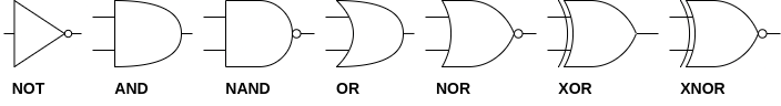
- VHDL Yes, in VHDL you can write AND, OR, NOT and so on, forcing thus the synthesizer to allocate exactly that logic gate, connected as you want.
- Verilog Same as VHDL :)
- SystemVerilog Same as Verilog :)
NOTE: When hardware is described at the logic level probably many simplifications can be operated, to save space and reduce the number of gates. This is not done by the designer at this step but later in the design, when optimization is run on the whole design. At this level, the engineer can perform some gate reduction using manual analysis but they are basic compared to the very advanced optimization algorithm run by synthesis tools. This argument will be covered in the next articles.
Circuital level
Circuital level design is not done on the whole IC! This would be crazy! It is used to design just some parts of the circuit (logic gates, flipflops, latches, single transistors and so on) that will be added to the cell library (the crossing point between the netlist made of signals and logic devices and the actual IC physical design). The EDA tool will take the best cell from such a library and place it on the layout.
- SPICE (Simulation Program with Integrated Circuit Emphasis) The SPICE language is widely known and used to represent circuits and model electronic devices. It is used for simulation, with small differences in the syntax and features from simulator to simulator. Note that SPICE is not capable of leading information about the design of a whole IC; it is rather used to simulate cells, gates, and transistors to be successively implemented by the physical design of the circuit: usually, engineers use SPICE to simulate gates and other components of the library to see if they are suitable for their purposes.
Physical level
- LEF (Library Exchange Format), DEF (Design Exchange Format)
- GDSII (Graphic Design System)
Conlcusions
In the next articles VHDL will be introduced, just to give an idea of what an HDL practically is, with some examples and a detailed description of its features.
Share this page


Comments
Be polite and respectful in the comments section. In case of doubts, read this before posting.
Posted comments ⮧
Comment section still empty.
INDEX
INFO
STATISTICS
PREVIOUS ARTICLE
NEXT ARTICLE
CONTACTS
SHARE