➔ Index of ⦁ Introduction to Digital Electronics ⦁
Your first VHDL lesson
VHDL is widely used for the description of digital hardware. Here, it is briefly introduced to provide an idea of its features and basic syntax.
Introduction
In the world of digital design, creating electronic circuits that perform specific functions is a crucial aspect. VHDL, which stands for Very High-Speed Integrated Circuit Hardware Description Language, is a powerful tool used for designing and describing digital systems. Developed in the 1980s, VHDL has become a standard in electronic design and is employed in telecommunications, aerospace, and consumer electronics.
VHDL is a hardware description language used to model and simulate electronic systems. It enables engineers to design and document the behaviour of digital circuits before they are implemented in hardware. Essentially, VHDL allows designers to describe the functionality of a digital circuit at various levels of abstraction, from a high-level system description to a detailed gate-level representation.
General syntax rules
VHDL is a versatile hardware description language, maybe a little older than its brother Verilog, but still a good starting point to introduce someone to VLSI design from architectural to gate level. It is simple and intuitive, with a few extra features and supported by many open-source simulators. Some general rules are listed below:
- Case sensitivity VHDL is case INsensitive!!! Use upper and lower case just for better code readability but remember that 'MYSIGNAL' and 'mysignal' will be interpreted as the same element
- Line ends Each line ends with a semicolon, except for some special cases that are described after in this article
- Single line comments Each comment starts with two dashes '--' and it ends at the end of the line
- Multiple line comments There is no way to have comments on multiple lines like in some programming languages; you have to comment each line at its beginning
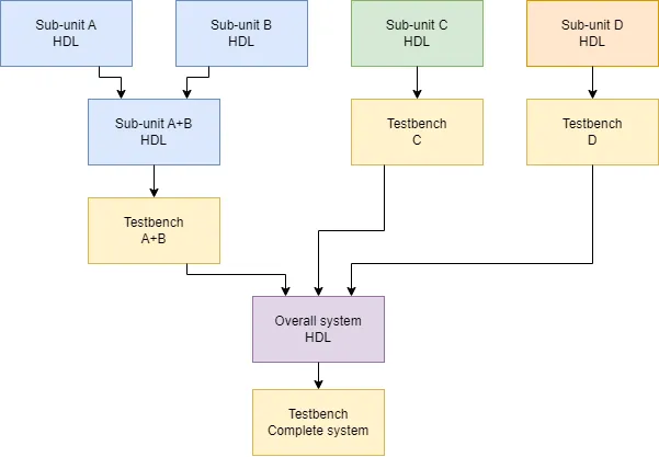
- Files structure If your project is made of more than one file, you should specify one entity (the equivalent of class in programming languages) per file
- File names and entities It is good practice to define one entity only in each .vhd file. Use the same entity name for the file; this is important for entity recognition in workspaces!
- Code structure As shown later in this article, each VHDL file can be divided into three sections: library definition, entity description and entity internal design. Go on with the reading to learn more
VHDL structure
Entities and Architectures:
VHDL uses a modular approach to design, where entities represent the interface of a module, and architectures define the internal implementation. Entities specify the inputs, outputs, and modes of operation, while architectures provide the details of how the module works.
Signals and variables
Signals are used to model the data flow between different parts of a design, while variables are used for temporary storage within processes. Understanding the proper use of signals and variables is crucial for effective VHDL design.
Processes
Processes in VHDL encapsulate a set of sequential statements that describe the behaviour of a circuit. Sequential statements are executed one after the other, allowing designers to model the flow of time in a digital system.
Concurrent statements
VHDL supports concurrent statements that enable the description of parallel processes. Concurrent statements, such as concurrent signal assignment, provide a way to model the simultaneous execution of operations.
Data Types
VHDL includes a variety of data types, such as bit, bit vector, integer, and real, to represent different types of information in a digital system.
Libraries and Imports
Before writing any hardware, you must say which libraries you want to use in your project. To do this, you have to add some of the following lines (or other ones) at the beginning of each file of your project
0
1
2
3
4
5
6
7
8
9
library IEEE;
use IEEE.std_logic_1164.all;
use IEEE.std_logic_arith.all;
use IEEE.std_logic_unsigned.all;
use IEEE.std_logic_signed.all;

library STD;
use STD.textio;

use WORK.all;
Keyword 'library' points to a library containing many files; 'use' is, instead, necessary to say which library file we want to include in our project, thus making all its internal definitions available inside our VHDL file. '.all' means that the whole library file must be included, with all its definitions.
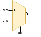
In the following, we will see how to describe a combinational circuit, in particular a 2-to-1 multiplexer. Some of the previously included library files will be useless since they don't contain relevant definitions for our simple component.
Entity definition
Entity is the main constitutive block of a VHDL file: it contains the description of input and output signals with, if needed, the definition of support variables, not used for synthesis but just for component description and, eventually, instantiation. In the entity definition section, you must describe the block you are designing as a black box, clarifying how other blocks will interact with this one. Entity of our 2-to-1 multiplexer is defined as shown below:
0
1
2
3
4
5
6
entity MUX21_GENERIC is
	Generic(N: integer := 32);
	Port (one:	In	std_logic_vector(N-1 downto 0);
	      zero:	In	std_logic_vector(N-1 downto 0);
	      sel:	In	std_logic;
	      Y:	Out	std_logic_vector(N-1 downto 0));
end MUX21_GENERIC;
Define in 'Generic' section all support variables used during component instantiation; use In or Out to define the signal direction; use 'N-1 downto 0' to define a bus with bits enumerated from MSB down to LSB. As you can see, VHDL syntax is pretty intuitive and straightforward.
Architecture: define how your entity works
Behavioural description
Here is where all the black magic happens: now you have to describe at a behavioural, RTL or gate level your digital circuit. We will start with a behavioural description of the multiplexer.
0
1
2
3
4
5
6
7
8
9
10
architecture BEHAVIORAL of MUX21_GENERIC is
begin
    behavior : process (one,zero,sel)
    begin
    	if sel='1' then
    		Y <= one;
    	elsif sel='0' then
    		Y <= zero;
   		end if;
    end process;
end BEHAVIORAL;
The keyword 'architecture' marks the beginning of the file where the circuit is described; you have to specify the name of the architecture and the entity it is related to. Then, since we are writing a behavioural description, you have to use a 'process': the programmatic description of the output behaviour based on the input states, sensitive to changes of all those signals placed inside parenthesis. '<=' is the assignment operator in VHDL, used to, let's say, write a logic value on a signal line. Note that every construct must terminate with an 'end' expression.
This description is called behavioural and the code works like this: whenever the input signals one, zero or sel change, 'behavior' process is recalled and 'Y' output is updated with the right input.
Gate-level description
We can do the same thing using a different approach: gate-level hardware description is good when you want to see which logic gates are instantiated. Take a look to the following code:
0
1
2
3
4
5
architecture GATEL of MUX21_GENERIC is
begin
    muxgen : for i in N-1 downto 0 generate
        Y(i) <= (one(i) and sel) or (zero(i) and not(sel));
    end generate;
end GATEL;
As you can see, there is no 'process' defined; instead, a 'generate' statement is used: this instructs the synthesis tool to add the AND, OR and NOT gates and connect them as specified. The 'generate' statement can be seen as a creation operation that automatically instantiates a set of gates in the desired manner; it's wrong to think it as a loop since gate or component generation is done once, whereas loops are executed sequentially.
Complete MUX21_BEHL.vhd file
Behaviour level MUX21_BEHL.vhd description
0
1
2
3
4
5
6
7
8
9
10
11
12
13
14
15
16
17
18
19
20
21
22
23
library IEEE;
use IEEE.std_logic_1164.all;
use WORK.all;


entity MUX21_BEHL is
	Generic(N: integer := 32);
	Port (one:	In	std_logic_vector(N-1 downto 0);
	      zero:	In	std_logic_vector(N-1 downto 0);
	      sel:	In	std_logic;
	      Y:	Out	std_logic_vector(N-1 downto 0));
end MUX21_BEHL;

architecture BEHAVIORAL of MUX21_BEHL is
begin
    behavior : process (one,zero,sel)
    begin
    	if sel='1' then
    		Y <= one;
    	elsif sel='0' then
    		Y <= zero;
   		end if;
    end process;
end BEHAVIORAL;
Complete MUX21_GATL.vhd file
Gate level MUX21_GATL.vhd description
0
1
2
3
4
5
6
7
8
9
10
11
12
13
14
15
16
17
library IEEE;
use IEEE.std_logic_1164.all;
use WORK.all;

entity MUX21_GATL is
	Generic(N: integer := 32);
	Port (one:	In	std_logic_vector(N-1 downto 0);
	      zero:	In	std_logic_vector(N-1 downto 0);
	      sel:	In	std_logic;
	      Y:	Out	std_logic_vector(N-1 downto 0));
end MUX21_GATL;

architecture GATEL of MUX21_GATL is
begin
    muxgen : for i in N-1 downto 0 generate
        Y(i) <= (one(i) and sel) or (zero(i) and not(sel));
    end generate;
end GATEL;
Share this page


Comments
Be polite and respectful in the comments section. In case of doubts, read this before posting.
Posted comments ⮧
Comment section still empty.
INDEX
INFO
STATISTICS
PREVIOUS ARTICLE
NEXT ARTICLE
CONTACTS
SHARE