➔ Index of ⦁ Transmission Lines Theory ⦁
Transmission lines - Part IX: Examples
Some numerical example for transmission lines
Example1
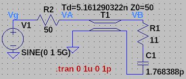
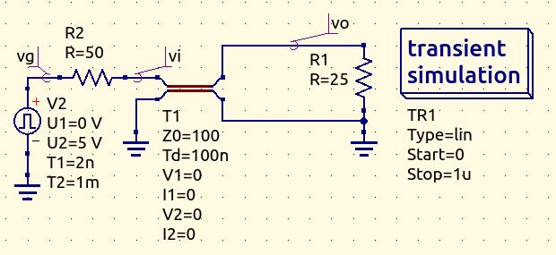
For this example, consider these data as input $$|V_g| = 5V \qquad R_g = 50Ohm \qquad Z_l = (11-18j)Ohm$$ $$Z_{\infty} = 50Ohm \qquad v_f = 217000000\frac{m}{s} \qquad l = 1.12m \qquad f=5GHz$$ Find the voltage at the V(A) and V(B) sections, showing all the passages. Here on the left, you can see the equivalent circuit for this transmission line.
TL parameters
$$k = \frac{2\pi}{\lambda} = \frac{2\pi f}{v_f} = \frac{5}{0.217}\pi\frac{rad}{m}$$ $$T_d = \frac{l}{v_f} = \frac{1.12}{217000000} s$$ $$C = \frac{1}{2\pi f X_l}$$
Gamma at B section
$$\Gamma_B = \frac{Z_l-Z_{\infty}}{Z_l+Z_{\infty}} = \frac{11-18j-50}{11-18j+50} = \frac{-39-18j}{61-18j}$$
Gamma and Z at A section
Now we can calculate Z starting from gamma $$\Gamma_A = \Gamma_B e^{-2jkl} = \frac{-39-18j}{61-18j} e^{-j\frac{11.2}{0.217}\pi}$$ $$ZA = Z_{\infty}\frac{1+\Gamma_A}{1-\Gamma_A}$$ or gamma starting from Z; the two methods are equivalent, use the one you prefer $$Z_A = \frac{Z_l - Z_{\infty}jtan(kz)}{1 - Z_l Y_{\infty}jtan(kz)} = \frac{(11-18j)-50jtan(-\frac{5.6}{0.217}\pi)}{1-(11-18j)0.02jtan(-\frac{5.6}{0.217}\pi)}$$ $$\Gamma_A = \frac{Z_A - Z_{\infty}}{Z_A + Z_{\infty}} = \frac{\frac{(11-18j)-50jtan(-\frac{5.6}{0.217}\pi)}{1-(11-18j)0.02jtan(-\frac{5.6}{0.217}\pi)}-50}{\frac{(11-18j)-50jtan(-\frac{5.6}{0.217}\pi)}{1-(11-18j)0.02jtan(-\frac{5.6}{0.217}\pi)}+50}$$
Voltage at section A
$$V_A = V_g \frac{Z_A}{Z_A+Z_g}$$
Voltage at section B (at load)
$$V_l = V_l^+ (1+\Gamma_B) = V_A^+ e^{-jkl} (1+\Gamma_B) = \frac{V_A}{1+\Gamma_A} (1+\Gamma_B) e^{-jkl}$$
Python3 code
Use Python or equivalent language to solve these problems; it is very difficult and risky to do everything by hand. Down below is the code that solves this example.
0
1
2
3
4
5
6
7
8
9
10
11
12
13
14
15
16
17
18
19
20
21
22
23
24
25
26
27
28
29
30
31
32
33
34
35
36
37
38
39
40
41
42
from math import *
from cmath import *

Vg = 1
Rg = 50
Zl = 11-18j
Zinf = 50
vf = 217000000
l = 1.12
f = 5000000000

print("Load capacitance [F] ",1/2/pi/f/18)
print("Line delay [s]",l/vf)

k = 2*pi*f/vf
print("k [rad/m]",k)

gammaB = (Zl-Zinf)/(Zl+Zinf)
print("gammaB ",gammaB)

gammaA1 = gammaB*e**(-2j*k*l)
print("gammaA1 ",gammaA1)
ZA1 = Zinf*(1+gammaA1)/(1-gammaA1)
print("ZA1 ",ZA1)

ZA2 = (Zl-1j*Zinf*tan(-k*l))/(1-1j*Zl*(1/Zinf)*tan(-k*l))
print("ZA2 ",ZA2)

gammaA2 = (ZA2-Zinf)/(ZA2+Zinf)
print("gammaA2 ",gammaA2)

VA = Vg*ZA2/(ZA2+Rg)
print("VA ",polar(VA))

VA_plus = VA/(1+gammaA2)
print("VA_plus ",polar(VA_plus))

VB_plus = VA_plus*e**(-1j*k*l)
print("VB_plus ",polar(VB_plus))

VB = VB_plus*(1+gammaB)
print("VB ",polar(VB))
Solution
Numerical solutions are $$V_A = 0.8376728027570334e^{0.004012860094463412j} V \rightarrow |V_A| = 0.8376728027570334 \quad \angle V_A = 0.23°$$ $$V_B = 0.3316811133294016e^{0.48079221062116045j} V \rightarrow |V_B| = 0.3316811133294016 \quad \angle V_B = 27.55°$$ Let's rewrite the expressions in the time domain $$V_A(t) = 0.8376728027570334 \cdot cos(2\pi5GHz \ t + 0.004012860094463412)$$ $$V_B(t) = 0.3316811133294016 \cdot cos(2\pi5GHz \ t + 0.48079221062116045)$$ Now, look at the circuit simulated with LTspice and its result. They confirm the calculations (15.19ps over 200ps are 27.55° circa of phase delay).

Example2
For this example, consider these data as input $$|V_g| = 5V \qquad R_g = 50Ohm \qquad Z_l = (30-20j)Ohm$$ $$Z_{\infty} = 50Ohm \qquad v_f = 200000000\frac{m}{s} \qquad l = 4.3m \qquad f=10GHz$$ Find the voltage at the V(A) and V(B) sections, showing all the passages. Here on the left, you can see the equivalent circuit for this transmission line.
TL parameters
$$k = \frac{2\pi}{\lambda} = \frac{2\pi f}{v_f} = 100\pi \frac{rad}{m}$$
Gamma at B section
$$\Gamma_B = \frac{Z_l-Z_{\infty}}{Z_l+Z_{\infty}} = \frac{30-20j-50}{30-20j+50} = -\frac{3+5j}{17}$$
Gamma at A section
Now we can calculate Z starting from gamma $$\Gamma_A = \Gamma_B e^{-2jkl} = -\frac{3+5j}{17} e^{-j200\pi \cdot 4.3} = -\frac{3+5j}{17} e^{-860j\pi} = -\frac{3+5j}{17}$$ $$Z_A = Z_{\infty}\frac{1+\Gamma_A}{1-\Gamma_A}$$ or gamma starting from Z; the two methods are equivalent, use the one you prefer $$Z_A = \frac{Z_l - Z_{\infty}jtan(kz)}{1 - Z_l Y_{\infty}jtan(kz)} = \frac{(30-20j)-50jtan(-430\pi\cdot 4.3)}{1-(30-20j)0.02jtan(-430\pi\cdot 4.3)} = (30-20j) Ohm$$ $$\Gamma_A = \frac{Z_A - Z_{\infty}}{Z_A + Z_{\infty}} = \frac{30-20j-50}{30-20j+50} = -\frac{3+5j}{17}$$ They are the same with both methods. The calculations are correct.
Voltage at section A and B
$$V_A = V_g \frac{Z_A}{Z_A+Z_g} = 5 \frac{30-20j}{30-20j+50}$$ $$V_l = V_l^+ (1+\Gamma_B) = V_A^+ (1+\Gamma_B) e^{-jkl} = \frac{V_A}{1+\Gamma_A} (1+\Gamma_B) e^{-jkl}$$
Solution
Again, use the previous Python script to solve this problem, just change the values at the beginning with the new ones: voltages are $$V_A = 2.1861865804881635e^{-0.343023940420717j}$$ $$V_B = 2.1861865804880147e^{-0.34302394042061535j}$$ In the time domain these two expressions become $$V_A(t) = 2.1861865804881635 \cdot cos(2\pi 10GHz \ t - 0.343023940420717)$$ $$V_B(t) = 2.1861865804880147 \cdot cos(2\pi 10GHz \ t - 0.34302394042061535)$$ Down below you can see the LTspice simulation result: delay between Vg and VA or VB is 5.576ps which, at 10GHz(100ps), corresponds to a phase delay of 0.35rad (20°) circa.

Share this page


Comments
Be polite and respectful in the comments section. In case of doubts, read this before posting.
Posted comments ⮧
I found this page very useful! Can you add an example where the transmission line has an impedance mismatch in the middle?
INDEX
INFO
STATISTICS
PREVIOUS ARTICLE
CONTACTS
SHARE