➔ Index of ⦁ Transmission Lines Theory ⦁
Transmission lines - Part VII: TL notable cases
Numerical analysis of some transmission lines notable cases, under various load impedance conditions
Input data
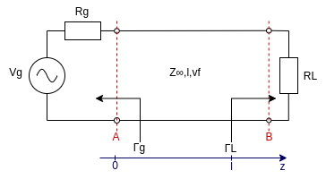
For all the next notable cases, the following input data apply: $$f = 10GHz$$ $$|V_g| = 10V$$ $$l = 10m$$ $$Z_{\infty} = 50Ohm$$ $$Z_g = 50Ohm$$ $$v_p = 2 \cdot 10^ 8 \ m \ s^{-1}$$ $$k = \frac{2\pi f}{v_p} = 314.1592653589793 \ rad \ m^{-1}$$ All the calculations are done under the assumption of standing wave. For all the cases reflection coefficient at load, reflection coefficient at the generator, and voltages at sections A and B.
Use the scheme on the left as a reference.
NOTE: the number of decimals used is very high because since I'm using radiants, any rounding or truncation can give imprecise and inaccurate results.
Matched load impedance
In this case we have that the load impedance is equal to the line characteristic impedance, so $$Z_L = Z_{\infty} = 50Ohm$$ Let's calculate the reflection coefficient at load: $$\Gamma_B = \Gamma_L = \frac{Z_L - Z_{\infty}}{Z_L + Z_{\infty}} = \frac{50Ohm - 50Ohm}{50Ohm + 50Ohm} = 0$$ Since the reflection coefficient is 0 at load, it is 0 also close to the generator. In this case, there is only the forward travelling wave along the line. $$\Gamma_A = \Gamma_L e^{-2jkl} = 0$$ Line impedance at section A is $$Z_A = \frac{Z_L - Z_{\infty}jtan(kz)}{1-Z_L Y_{\infty}jtan(kz)}; \qquad Z_L=Z_g=Z_{\infty} \qquad Z_A = \frac{Z_L (1-jtan(kz))}{1-jtan(kz)} = Z_L$$ The voltage at section A is the sum of the forward and backward travelling waves $$V_A = V_A^+ + V_A^- = V_A^+ (1+\Gamma_A) = V_A^+ = V_g \frac{Z_A}{Z_A + Z_g} = \frac{1}{2} V_g = \frac{|V_g|}{2} cos(\omega t) = 5 cos((2\pi \cdot 10GHz) \ t) V$$ The voltage at section B is $$2\pi : \frac{1}{f} = \phi : \frac{l}{v_p} \quad \rightarrow \quad \phi=\frac{2\pi l f}{v_p} = kl \sim 3141.5926535897934$$ Note that the product kl is an even multiple of pi (it's pi*1000) so cosine with that phase is equal to cosine: at both sections A and B we have the same modulus with the same phase! $$V_B = V_B^+ + V_B^- = V_B^+ (1+\Gamma_L) = V_B^+ = V_A^+ e^{-jkl} = \frac{V_A}{(1+\Gamma_A)} e^{-jkl} = 5 cos((2\pi \cdot 10GHz) \ t) V$$
Short circuit load impedance
In this case we have that the load impedance is equal to 0Ohm, so $$Z_L = 0Ohm$$ Let's calculate the reflection coefficient at load: $$\Gamma_B = \Gamma_L = \frac{Z_L - Z_{\infty}}{Z_L + Z_{\infty}} = \frac{0Ohm - 50Ohm}{0Ohm + 50Ohm} = -1$$ The reflection coefficient is negative at load, which means that the incident wave is completely reflected and inverted. Let's calculate which is its value at generator (section A) - (note that the argument of the exponential is pi multiplied by 2000, which is equivalent to a phase of 0rad) $$\Gamma_A = \Gamma_L e^{-2jkl} = -1 e^{-2 \cdot j \cdot \pi\cdot 100 \cdot 10} = -1 e^{-\pi \cdot 2000j} = -1$$ Line impedance in section A is (note that the argument of tan is pi multiplied by 1000) $$Z_A = \frac{Z_L - Z_{\infty}jtan(-kz)}{1-Z_L Y_{\infty}jtan(-kz)} = \frac{-Z_{\infty}jtan(-kz)}{1} = -50jtan(-\pi \cdot 1000) Ohm = 0Ohm$$ Let's double-check: ZA can be used to calculate ΓA as follows; this value must be the same as previously calculated $$\Gamma_A = \frac{Z_A - Z_{\infty}}{Z_A + Z_{\infty}} = \frac{(-50jtan(-\pi \cdot 1000)-50)}{(-50jtan(-\pi \cdot 1000)+50)} = -1 \frac{1+jtan(-\pi \cdot 1000)}{1-jtan(-\pi \cdot 1000)} = $$ $$ = -1 \frac{1+j\frac{sin(-\pi \cdot 1000)}{cos(-\pi \cdot 1000)}}{1-j\frac{sin(-\pi \cdot 1000)}{cos(-\pi \cdot 1000)}} = -1 \frac{cos(-\pi \cdot 1000)+jsin(-\pi \cdot 1000)}{cos(-\pi \cdot 1000)-jsin(-\pi \cdot 1000)} = $$ $$ = -1 \frac{e^{-\pi \cdot 1000j}}{e^{\pi \cdot 1000j}} = -1 e^{-2 \cdot \pi \cdot 1000j} = -1 e^{-\pi \cdot 2000j} = -1$$ Now we have to calculate the voltage at section A, at the interface between the generator and the transmission line. $$V_A = V_A^+ + V_A^- = V_A^+ (1+\Gamma_A) = 0V$$ The voltage at section B is instead $$V_B = V_B^+ + V_B^- = V_B^+ (1+\Gamma_L) = 0V$$ Voltage is a fixed 0V at both ends.
Open circuit load impedance
In this case we have that the transmission line is not terminated, so $$Z_L = \infty Ohm$$ Let's calculate the reflection coefficient at load: $$\Gamma_L = \frac{Z_L - Z_{\infty}}{Z_L + Z_{\infty}} = \frac{\infty - 50Ohm}{\infty + 50Ohm} = 1$$ The reflection coefficient is unitary so the whole incident wave is reflected. Let's calculate which is its value at the generator (section A) $$\Gamma_A = \Gamma_L e^{-2jkl} = 1 e^{-2 \cdot j \cdot \pi \cdot 100 \cdot 10} = 1 e^{-2\pi \cdot 1000j} = 1$$ Line impedance at section A is $$Z_A = \frac{Z_L - Z_{\infty}jtan(-kz)}{1-Z_L Y_{\infty}jtan(-kz)} = \frac{Z_L}{-Z_L Y_{\infty}jtan(-kz)} = -\frac{Z_{\infty}}{jtan(-kz)} = \frac{50j}{tan(-\pi \cdot 1000)} Ohm = \infty Ohm$$ Let's double-check: ZA can be used to calculate ΓA as follows; this value must be the same as previously calculated $$\Gamma_A = \frac{Z_A - Z_{\infty}}{Z_A + Z_{\infty}} = \frac{\frac{50j}{tan(-\pi \cdot 1000)} - 50}{\frac{50j}{tan(-\pi \cdot 1000)} + 50} =$$ $$ = \frac{ \frac{jcos(-\pi \cdot 1000)}{sin(-\pi \cdot 1000)} - 1}{ \frac{jcos(-\pi \cdot 1000)}{sin(-\pi \cdot 1000)} + 1} = \frac{ jcos(-\pi \cdot 1000) - sin(-\pi \cdot 1000)}{ jcos(-\pi \cdot 1000) + sin(-\pi \cdot 1000)} = $$ $$\frac{ cos(-\pi \cdot 1000) + jsin(-\pi \cdot 1000)}{ cos(-\pi \cdot 1000) - jsin(-\pi \cdot 1000)} = \frac{e^{-\pi \cdot 1000j}}{e^{\pi \cdot 1000j}} = e^{-2\pi \cdot 1000j} = 1$$ Now we have to calculate the voltage at section A, at the interface between the generator and the transmission line. $$V_A = V_A^+ + V_A^- = V_A^+ (1+\Gamma_A) = V_g \frac{Z_A}{Z_A + Z_g} = |V_g|cos(\omega t) \frac{Z_A}{Z_A + Z_g} = 10cos((2\pi \cdot 10GHz)t) V$$ The voltage at section B is instead (note that, again, the additional phase due to kl in the exponent is an even multiple of pi so it doesn't change the cosine) $$V_B = V_B^+ + V_B^- = V_B^+ (1+\Gamma_L) = V_A^+ e^{-jkl} (1+\Gamma_L) = \frac{V_A}{(1+\Gamma_A)}e^{-jkl} (1+\Gamma_L) = \frac{10cos((2\pi \cdot 10GHz)t) }{(1+\Gamma_A)}e^{-jkl} (1+\Gamma_L) = 10cos((2\pi \cdot 10GHz)t) V$$
Navigate
Share this page


Comments
Be polite and respectful in the comments section. In case of doubts, read this before posting.
Posted comments ⮧
Comment section still empty.
INDEX
INFO
STATISTICS
PREVIOUS ARTICLE
NEXT ARTICLE
CONTACTS
SHARE