➔ Index of ⦁ Introduction to Digital Electronics ⦁
Your first VHDL testbench
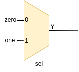
In the previous articles, I provided two simple HDLs of a 2-to-1 mux and a brief introduction to simulation tools; now, it's time to simulate! Let's write a simple VHDL test-bench, to understand how components are tested and verified after the design phase.
Testbenches
Testbenches play a pivotal role in the design and verification process. A testbench is a simulation environment that validates the functionality of a digital design before it is implemented in hardware. This article explores their significance and how they contribute to the robustness and reliability of digital systems.
The primary purpose of a testbench is to verify the correctness of a digital design. It allows designers to subject their circuits to various stimuli, observe their responses, and ensure that they meet the specified requirements. Testbenches help catch errors, ensure design stability, and ultimately lead to more reliable hardware implementations.
Testbenches are indispensable tools in the digital design process. They facilitate rigorous testing, error identification, and verification of complex digital circuits. A well-constructed testbench ensures the reliability and accuracy of the final hardware implementation, making it a critical aspect of VHDL-based design methodologies.
Write a testbench
A VHDL testbench typically consists of two main components: the testbench entity and the testbench process. Create a new file called tb.vhd and write the following lines (always the same library definition)
0
1
library IEEE;
use IEEE.std_logic_1164.all;
Testbench Entity
This is a separate VHDL entity that instantiates the primary design entity, creating an environment for simulation. It includes signal declarations, component instantiations, and other configurations necessary for simulation. In this case, entity declaration is empty since there is no need of additional information for our simulation.
0
1
entity tb is
end tb;
Testbench Process
The testbench process is where stimulus is applied to the design under test (DUT). It includes test vectors, clock generation, and other simulation control mechanisms. Similarly to component definition, testbench process is placed inside an 'architecture' section.
0
1
2
3
4
5
6
7
8
9
10
11
12
13
14
15
16
17
18
19
20
21
22
23
24
25
26
27
28
29
30
31
32
33
34
35
36
37
38
39
40
41
42
43
44
45
architecture behav of tb is
    component MUX21_BEH
        port (one:	In	std_logic_vector;
              zero:	In	std_logic_vector;
              sel:	In	std_logic;
              Y:	Out	std_logic_vector);
    end component;
    constant N : integer := 32;
    signal in0 : std_logic_vector(N-1 downto 0);
    signal in1 : std_logic_vector(N-1 downto 0);
    signal Y   : std_logic_vector(N-1 downto 0);
    signal sel : std_logic;

    begin
        DUT: MUX21_BEH  generic map (N => N)
                        port map (one => in1, zero => in0, sel => sel, Y => Y);

        process
        begin
            in0 <= std_logic_vector(to_unsigned(4234, N));
            in1 <= std_logic_vector(to_unsigned(1, N));
            sel <= '0';
            wait for 5 ns;
            in0 <= std_logic_vector(to_unsigned(58474, N));
            in1 <= std_logic_vector(to_unsigned(555, N));
            sel <= '1';
            wait for 5 ns;
            in0 <= std_logic_vector(to_unsigned(1325, N));
            in1 <= std_logic_vector(to_unsigned(545, N));
            sel <= '1';
            wait for 5 ns;
            in0 <= std_logic_vector(to_unsigned(1111, N));
            in1 <= std_logic_vector(to_unsigned(2, N));
            sel <= '0';
            wait for 5 ns;
            in0 <= std_logic_vector(to_unsigned(9876, N));
            in1 <= std_logic_vector(to_unsigned(3456, N));
            sel <= '1';
            wait for 5 ns;
            in0 <= std_logic_vector(to_unsigned(546, N));
            in1 <= std_logic_vector(to_unsigned(0, N));
            sel <= '0';
            wait for 5 ns;
            wait;
        end process;
end behav;
As you can see from the code above, the first thing to do in a testbench consists in defining all the device under tests using the 'component' statement, before the 'begin' keyword; then you have to define constants and signals.
After 'begin' you have to create an instance of your DUT, mapping both generic and port to the previously defined constants and variable (this is equivalent to a physical connection between a signal generator and you DUT); use the '=>' operator to connect them.
Finally, you have to define a process, the section where the entire component simulation is performed through automatic or iterative stimuli application to input ports; in this case, some integer numbers are cast to unsigned and then converted to std_logic_vector so that they could be applied to input ports defined in the same way. When the testbench is executed, you'll be able to inspect all those signals connected to DUT and check is the results are correct.
In a process, the 'wait' statement is used to wait for a defined or undefined time to pass; this keyword should be used only in testbenches or post-processing files and not in component definition, since digital circuits behaviour is always described through states and transitions between them, independently from the time. As a general rule, do NOT use 'wait' in entities that are not testbenches.
Conclusions
If you didn't understand everything, don't worry, I always prefer an approach allowing you to make things by yourself before fully comprehending everything. At the end of the last articles you should have three files: tb.vhd, mux21_behl.vhd and mux21_gatl.vhd: the next step consists in learning how to use GHDL+GTKwave and simulating them.
Navigate
Share this page


Comments
Be polite and respectful in the comments section. In case of doubts, read this before posting.
Posted comments ⮧
Comment section still empty.
INDEX
INFO
STATISTICS
PREVIOUS ARTICLE
NEXT ARTICLE
CONTACTS
SHARE