➔ Index of ⦁ Introduction to Electromagnetic Compatibility ⦁
Introduction to EMC: Mixers
Before discussing EMI test receivers and other EMC instruments, it is essential to understand what a mixer is and how it works. Let's dive deeper into this topic.
What is a mixer?
As the name suggests, the mixer is a circuit that combines two signals using transistors and amplifiers (active mixers) or diodes and passive components (passive mixers). An RF mixer is a non-linear electrical circuit that combines two input signals to produce new signals at different frequencies. The most important outputs from this process are the sum and difference of the frequencies of the input signals.
In every mixer, the following names can be found:
- RF - RadioFrequency: This is the input signal to be processed by the mixer. It may come from an antenna, an RF analogue module, a transmission line
- LO - Local Oscillator: This is the reference signal for the mixer. It is typically a very stable, temperature-independent, sinusoidal signal generated by a local oscillator
- IF - Intermediate Frequency: This is the name used to address one of the two main components of the output signal, i.e. the one at the lowest frequency. This signal can be filtered, amplified and processed by other components in an easier way because of its lower frequency
- SUM - Sum Frequency: This is the second component of the output signal, placed at higher frequency
Mixers are used to convert a signal to a lower or higher frequency for easier processing or transmission (frequency shifting), extract the original information signal from a modulated carrier wave (demodulation) or combine signals to encode information for transmission (modulation).
I placed an article about this topic here because it's mandatory to understand how they work before proceeding with EMI receivers.
Mixer working principle
Mixers exploit non-linearities in electronic components to perform multiplication between signals and obtain an output signal shifted to lower or higher frequencies. The principle behind this is shown below.
Let's define two signals: $$V_{RF}(t) = A_{RF}cos(2\pi f_{RF}t) $$ $$V_{LO}(t) = A_{LO}cos(2\pi f_{LO}t)$$
The output of the mixer is the following one: $$V_{OUT}(t) = V_{RF}(t) \cdot V_{LO}(t) $$ $$V_{OUT}(t) = A_{RF}cos(2\pi f_{RF}t) \cdot A_{LO}cos(2\pi f_{LO}t) = $$ $$= A_{RF}A_{LO}[cos(2\pi f_{RF}t) \cdot cos(2\pi f_{LO}t)] = $$ $$= \frac{1}{2}A_{RF}A_{LO}[cos(2\pi t (f_{RF}-f_{LO})) + cos(2\pi t (f_{RF}+f_{LO}))]$$
At the output of the mixer, we get two signals: the first one at the difference and the second at the sum of the two input frequencies. Typically, we want to use only one of the two and, eventually, remove all the spurious signals at other frequencies that entered the mixer. To do this, the use of filters at the input and output of the mixer becomes mandatory; however, since these filters are very complex and expensive, other solutions are implemented.
Mixers are bi-directional components; they can be utilized to down-convert (elaboration and processing) or up-convert (transmission) signals, according to the port used as input.
Example 1: straightforward down-conversion with high-side injection
We want to down-convert an RF signal at 850MHz, whereas the local oscillator LO runs at 900MHz. There is only one signal source and the rest of the spectrum contains negligible noise.
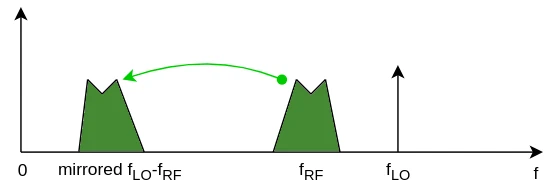
In this case, the mixer works with a high-side injection scheme, meaning that the LO frequency is higher than the RF frequency, so the spectrum of the output signal must be mirrored. At the output of the mixer, we get a signal that contains both the 1.75GHz and the 50MHz components. It is sufficient to filter out the high-frequency component using an LPF to get what we need.
Example 2: image frequency problem
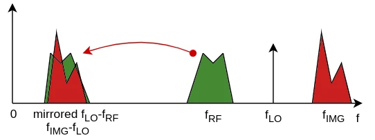
We want to down-convert an RF signal at 850MHz and the local oscillator LO runs at 900MHz. Unfortunately, the spectrum of the input signal contains spurious components from the environment and one of them comes at 950MHz. The mixer generates an output signal containing two sum components at 1.75GHz and 1.85GHz: they can be filtered easily. However, at 50MHz, we get a signal which is the sum of two components: |850-900|MHz, which is the real RF signal to down-convert and mirror, and |950-900|MHz, which is called 'image frequency'; once mixed, the two components can't be separated anymore and the final result of the down-conversion is not usable.
To avoid this, we need a combined use of a preselection filter and image rejection filters at the input of the mixer: they help to filter out unwanted noise and side bands and remove the image conversion problem.
The preselection filter reduces the amount of energy at the input of the mixer, simplifying the conversion, avoiding possible input overload and removing phantom effects. The image rejection filter, instead, prevents unwanted signals at the image frequency from entering the mixer; for this reason, it must be a very selective filter.
Image Rejection Ratio (IRR)
Every mixer (analogue mixers based on the superheterodyne principle) can remove the spectra at the image frequency, thanks to highly selective, precise and tunable band-pass input filters.
This capability is expressed as IRR (Image Rejection Ratio) and is typically expressed in dB. $$IIR = 20log\frac{|V_{out,IMG}|}{|V_{in,IMG}|}$$
To remove the image frequency problem, there are two approaches, based on the selection of IF:
High IF
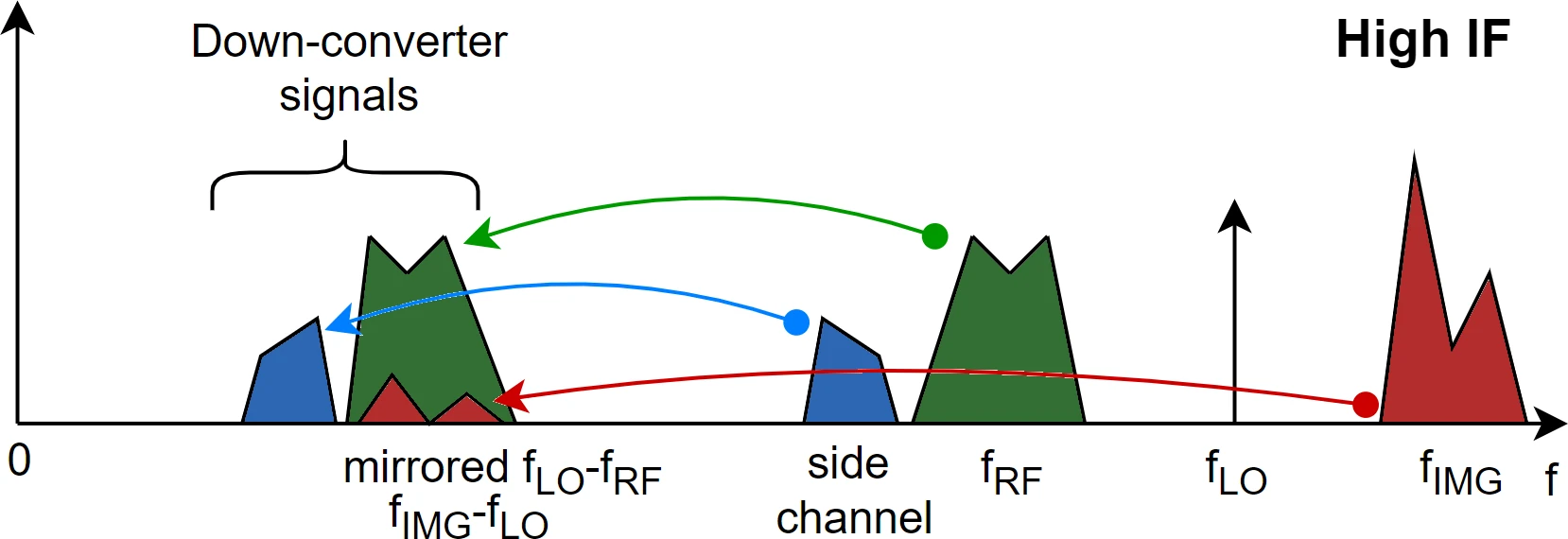
Choosing a high IF (meaning that there is a high difference between RF and LO), it becomes easier to filter out the image frequency before it enters the mixer using a simple low-pass filter. However, at higher IF, it is difficult to design a band-pass filter to isolate the desired signal from unwanted side bands.
In the image aside, the red spectrum at the image frequency is the one that can be easily removed with a low-pass filter. The signal distortion at IF due to IMG is relatively low, and negligible compared to the magnitude of the RF signal (green one). Since a simple low-pass filter is used, side bands (signals at frequencies close to RF) appear at IF too: they must be removed with a selective band-pass filter placed after the mixer.
Low IF
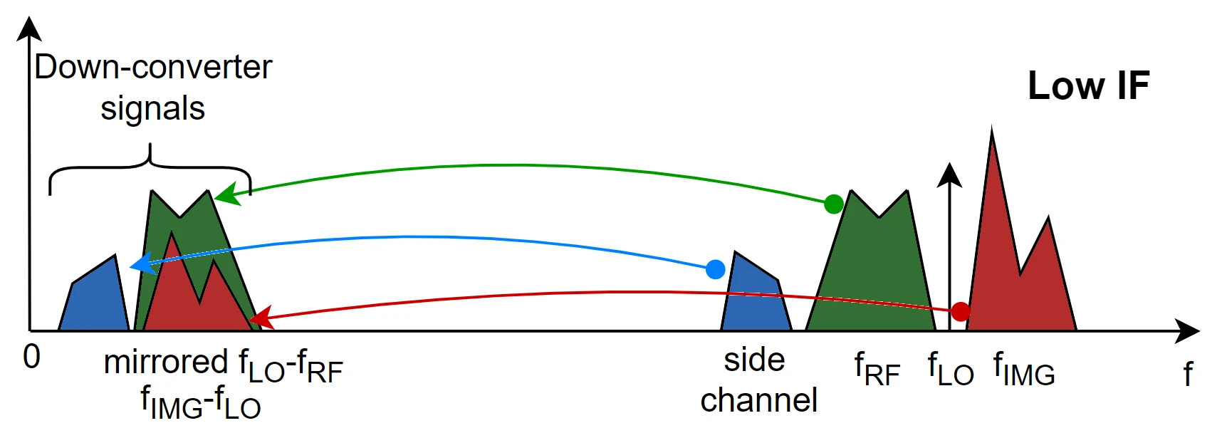
In this case, it's quite difficult to filter out the distortion introduced by the image frequency since the mixer input filter must have a very selective bandwidth (technically difficult to design). However, at lower IF frequencies, it's easy to design channel selection filters (highly selective band-pass filters) which are very stable and precise, reducing thus the distortion introduced by side bands.
Side bands removal
As explained, one of the most important aspects to manage is the choice of IF: a tradeoff between band-pass filter selectivity (after the mixer) and image frequency distortion (before the mixer) must be found. Take a look at the image aside:
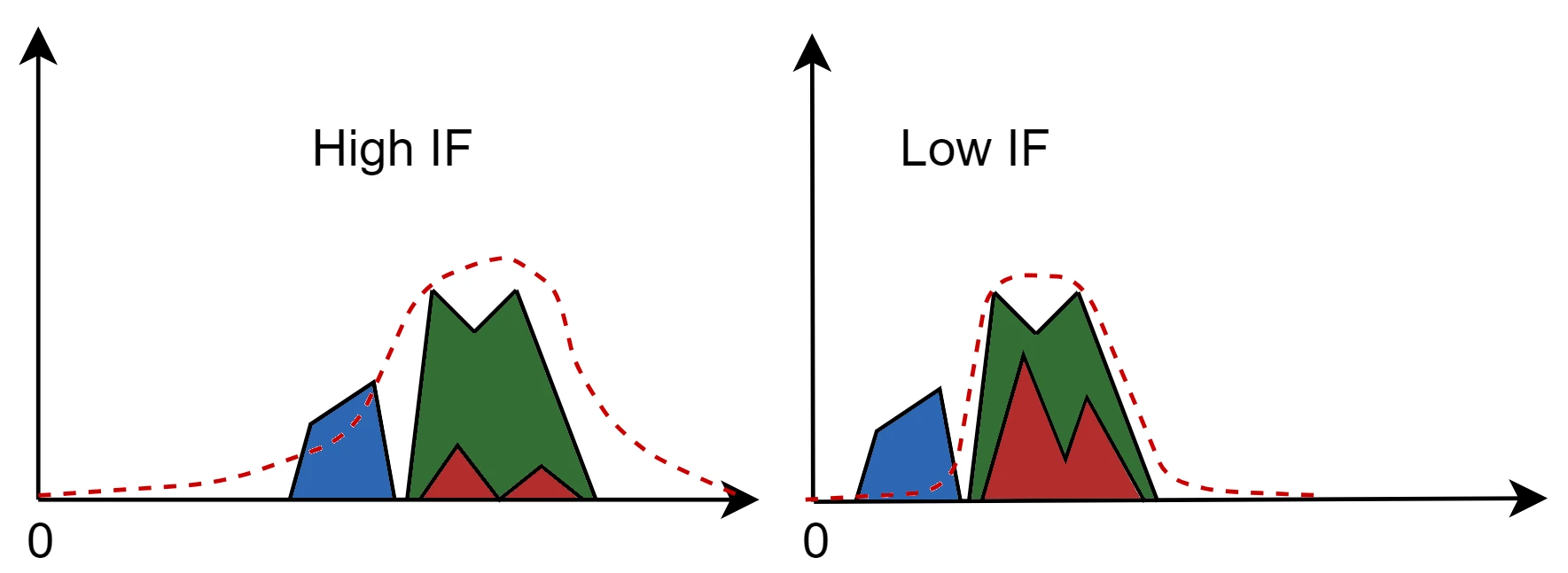
If IF is low, then the band-pass filter - whose mask is drawn in red - removes almost completely the spectrum of the sideband but the signal at the IMG frequency is slightly attenuated. On the other hand, if IF is high, the IMG frequency component in IF is negligible but the band-pass filter will not completely remove the components from the sideband.
Feed-through
Self-mixing products
Intermodulation products
Summary
More information on mixers will be provided in the next articles.
Share this page


Comments
Be polite and respectful in the comments section. In case of doubts, read this before posting.
Posted comments ⮧
Comment section still empty.
INDEX
INFO
STATISTICS
PREVIOUS ARTICLE
NEXT ARTICLE
CONTACTS
SHARE