
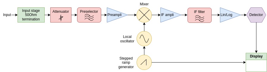
EMI receiver basic scheme
Let's start considering that there are two types of EMI receivers: superheterodyne-based and FFT-based receivers and they both can be used interchangeably; however in this article, I'm going to focus on the first type only. Moreover, don't confuse spectrum analyzers with EMI receivers! Their working principle is similar even if they show some constitutive differences.
Superheterodyne EMI receivers are pretty similar to a radio but the output of the IF block is sent to a Lin to Log amplifier and then to a detector rather than to a demodulator and then to an audio amplifier.
In the following the various blocks are explained.
Input stage
The input stage consists of a coaxial or similar connector with a (typically) 50Ohm termination impedance. Such a stage must be properly designed so that the lowest signal reflection is generated along the transmission line. Since EMI receivers must work in very noisy environments too, they also have input protections (pulse limiters) for high voltage/low energy spikes, so you can often find some ultra-low capacitance TVS (Transient voltage suppressor) at the instrument inputs. A very high-frequency filter may be found, to prevent unwanted noise from being amplified from the first amplifier.
Attenuator
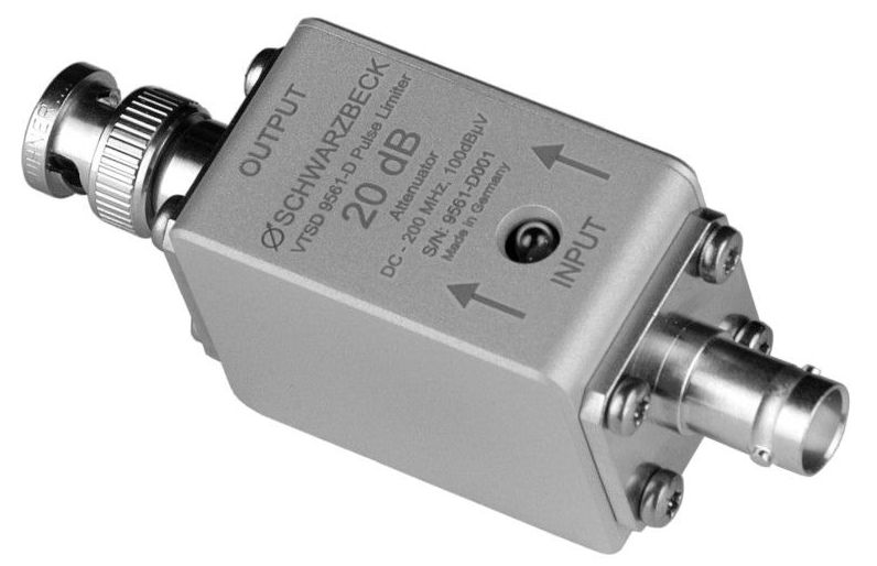
with integrated 20dB attenuator - Schwarzbeck
The attenuator is usually a passive device and in some cases an automatic circuit, able to detect the signal level and eventually attenuate it in case of too high voltage values: this is done to protect internal circuitry from overload (e.g. the input resistor can tolerate a maximum power dissipation) and not to saturate next amplifier outputs, which are designed to work with a defined maximum input signal amplitude. No attenuator would result in a constant and meaningless line shown on the display and, for older instruments, it could lead to permanent damage of the internal circuit.
Attenuators come in many types (T, PI, L and bridged-T attenuators) and will be discussed in the next articles since they deserve more attention.
Sometimes, if your circuit is very noisy or you want to add some additional protection to your receiver, external attenuators are available and they can be externally connected through the input port. Such attenuation can then be compensated so that the noise level plot on the screen of your instrument is still correct.
Preselector
spectral energy from the input signal and avoid erroneous conversion
A preselector is a tracking band-pass filter, used to select the frequency range one wants to scan, to:
1) remove compression (remove unwanted frequencies, higher or lower than the band under investigation, before they enter the pre-amplifier and sent to the mixer) and
2) remove outside-band noise which could overload the amplifier. Even if the in-band frequency components have a small amplitude, this may result in a saturated amplifier output.
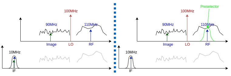
Concerning the first point, superheterodyne circuits are affected by the problem of image frequency. If you tune your LO at 85MHz and you have a 10MHz IF, then, all the spectrum will be downconverted so that LO goes to 0Hz and RF shifts down to IF (so the components at 95MHz are shifted to 10MHz); however also the components at RF 75MHz are downshifted and are converted to a 10MHz signal. If the input signal is not properly filtered through a preselector, you could find at the output of the mixer a superimposition of two signals, one coming from LO+IF and another from LO-IF. However, we are interested only in one of the two.
Preselector can be realized through electronically switched filter banks (filters working at fixed frequency ranges, switched in and out according to the scan frequencies) or tunable filters (hard to design and very delicate).
Preselector filter doesn't have a perfectly flat passband! However, the advantages are much more than the disadvantages so they are always used in EMI receivers.
Pre-amplifier
Pre-amplifier is a low-noise, high-gain stage. It is fundamental to properly feed the next stages with a signal level that can be elaborated by analogue and digital electronics. In EMI receivers, pre-amplifiers can be programmed with the desired gain, to get the
Mixer and local oscillator
The mixer is the heart of the EMI receiver: it consists of an active (transistor-based) or passive (diode-based) circuit used to shift the signal to lower frequencies, to make it processable and usable by the next stages.
Mixers introduce additional frequencies called "mixing products": they are caused by the
IF amplifier
IF filter
Detector
This is one of the most important parts blocks of an EMI receiver. There are various types of detectors, according to the kind of measurements one wants to do.
Share this page


Comments
Be polite and respectful in the comments section. In case of doubts, read this before posting.