➔ Index of ⦁ Introduction to Electromagnetic Compatibility ⦁
Introduction to EMC: Attenuators
What is an attenuator? Nothing really complicated but something that deserves our attention when working with EMI receivers
What is an attenuator
Attenuators are used in RF circuits to reduce the peak-to-peak voltage at the input stage before it enters the filter and amplifier stage. It is important since, under some conditions or in noisy environments, the amplifier output could be saturated by too high noise. Attenuators are typically simple passive devices but in some cases, more complex circuits can be found in literature or market products; they should introduce as low mismatch as possible, to avoid reflection; insertion loss is instead accurately calibrated and it must be considered when performing the measure.
Since attenuators are placed between two matched transmission lines, input and output impedances must be the same and both of them must match the transmission line impedance Z0; the output resistance must be calculated to get the desired attenuation.
Attenuators are symmetric, 2-ports, linear, passive devices. Attenuation factor K is defined as (IL is Insertion Loss in dB): $$K = 10^{\frac{IL[dB]}{20}}$$ Normalized Insertion Loss is $$IL_{norm} = K^{-1} = \frac{1}{10^{\frac{IL[dB]}{20}}} = 10^{-\frac{IL[dB]}{20}}$$ Detailed calculations are shown below for the various types of attenuators.
T attenuator
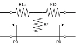
T attenuator is made of two series resistors and a centre parallel resistor. To work properly it must satisfy the following equalities $$\begin{cases} Z_{in} = Z_{out} = Z_{0} = (Z_{0}+Z_{1b})//Z_{2} + Z_{1a} = (Z_{0}+Z_{1a})//Z_{2} + Z_{1b} \\[2ex] IL_{norm} = 10^{-\frac{IL[dB]}{20}} = \frac{(Z_{0}+Z_{1b})//Z_{2}}{(Z_{0}+Z_{1b})//Z_{2} + Z_{1a}} \frac{Z_{0}}{Z_{0} + Z_{1b}} \end{cases}$$ Since the T attenuator is symmetric, linear and purely passive, the system can be rewritten as $$\begin{cases} R_{in} = (R_{0}+R_{1})//R_{2} + R_{1} = \frac{(R_0 + R_1)R_2}{R_0 + R_1 + R_2} + R_1 \\[2ex] 10^{-\frac{IL[dB]}{20}} = \frac{(R_0 + R_1)//R_2}{(R_0 + R_1)//R_2 + R_1} \frac{R_0}{R_0 + R_1} \end{cases}$$ Expanding parallel expression we get $$\begin{cases} R_{in} = \frac{R_0 R_2 + R_1 R_2 + R_0 R_1 + R_1^2 + R_2 R_1}{R_0 + R_1 + R_2} = \frac{2 R_1 R_2 + R_1^2 + R_0(R_1 + R_2)}{R_0 + R_1 + R_2} = R_0 \\[2ex] 10^{-\frac{IL[dB]}{20}} = \frac{\frac{(R_0 + R_1)R_2}{R_0 + R_1 + R_2}}{\frac{(R_0 + R_1)R_2}{R_0 + R_1 + R_2} + R_1} \frac{R_0}{R_0 + R_1} \end{cases}$$ Simplifying the first equation we get $$\begin{cases} 2 R_1 R_2 + R_1^2 = R_0^2 \\[2ex] K^{-1} = 10^{-\frac{IL[dB]}{20}} = \frac{(R_0 + R_1)R_2}{(R_0 + R_1)R_2 + R_1(R_0 + R_1 + R_2)} \frac{R_0}{R_0 + R_1} \end{cases}$$ $$\begin{cases} 2 R_1 R_2 + R_1^2 = R_0^2 \\[2ex] K = 10^{\frac{IL[dB]}{20}} = \frac{R_1^2 + 2 R_1 R_2 + R_0 R_1 + R_0 R_2}{R_0 R_2} = \frac{R_1^2}{R_0 R_2} + \frac{2 R_1}{R_0} + \frac{R_1}{R_2} + 1 \end{cases}$$ $$\begin{cases} R_2 = \frac{R_0^2 - R_1^2}{2 R_1} \\[2ex] K = \frac{2 R_1^3}{R_0 (R_0^2 - R_1^2)} + \frac{2 R_1(R_0^2 - R_1^2)}{R_0(R_0^2 - R_1^2)} + \frac{2 R_1^2 R_0}{R_0 (R_0^2 - R_1^2)} + 1 \end{cases}$$ $$\begin{cases} R_2 = \frac{R_0^2 - R_1^2}{2 R_1} \\[2ex] K = \frac{2 R_1}{R_0 - R_1} + 1 \end{cases}$$ Final result is $$\begin{cases} R_2 = R_0 \frac{2K}{K^2-1} \\[2ex] R_1 = R_0 \frac{K-1}{K+1} \end{cases}$$
PI attenuator
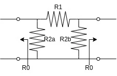
A PI attenuator is made of two parallel resistors and a central series resistor. To work properly it must satisfy the following equalities $$\begin{cases} Z_{in} = Z_{out} = Z_{0} = ((Z_{0}//Z_{2b})+Z_{1} ) // Z_{2a} = ((Z_{0}//Z_{2a})+Z_{1} ) // Z_{2b} \\[2ex] IL_{norm} = 10^{-\frac{IL[dB]}{20}} = \frac{Z_{0}//Z_{2b}}{Z_{0}//Z_{2b}+Z_{1}} \end{cases}$$ Since the T attenuator is symmetric, linear and purely passive, the system can be rewritten as $$\begin{cases} R_{in} = R_{out} = R_{0} = ((R_{0}//R_{2})+R_{1} ) // R_{2} = \frac{(\frac{R_{0}R_{2}}{R_{0}+R_{2}} + R_{1})R_{2}}{(\frac{R_{0}R_{2}}{R_{0}+R_{2}} + R_{1})+R_{2}} \\[2ex] IL_{norm} = 10^{-\frac{IL[dB]}{20}} = \frac{R_{0}//R_{2}}{R_{0}//R_{2}+R_{1}} \end{cases}$$ Expanding parallel expression we get $$\begin{cases} R_{in} = \frac{(R_0R_2+R_0R_1+R_1R_2)R_2}{R_0R_2+R_0R_1+R_1R_2+R_0R_2+R_2^2} = R_{0} \\[2ex] 10^{-\frac{IL[dB]}{20}} = \frac{R_0R_2}{R_0R_2+R_0R_1+R_2R_1} \end{cases}$$ Simplifying the first equation we get $$\begin{cases} R_0R_2^2+R_0R_1R_2+R_1R_2^2 = R_0^2R_2+R_0^2R_1+R_0R_1R_2+R_0^2R_2+R_0R_2^2 \\[2ex] 10^{-\frac{IL[dB]}{20}} = \frac{R_0R_2}{R_0R_2+R_0R_1+R_2R_1} \end{cases}$$ $$\begin{cases} R_1R_2^2 = R_0^2R_2+R_0^2R_1+R_0^2R_2 \\[2ex] KR_0R_2 = R_0R_2+R_0R_1+R_2R_1 \end{cases}$$ $$\begin{cases} R_1 = \frac{2R_0^2R_2}{R_2^2-R_0^2} \\[2ex] KR_0R_2 = R_0R_2+(R_0+R_2)\frac{2R_0^2R_2}{R_2^2-R_0^2} \end{cases}$$ $$\begin{cases} R_1 = \frac{2R_0^2R_2}{R_2^2-R_0^2} \\[2ex] K = 1+\frac{2R_0}{R_2-R_0} \end{cases}$$ Final result is $$\begin{cases} R_1 = R_0\frac{K^2-1}{2K} \\[2ex] R_2 = R_0\frac{K+1}{K-1} \end{cases}$$
L attenuator
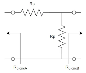
L attenuator is quite simple (it works like a voltage divider) but has some drawbacks. Input and output impedance are not the same so this attenuator is linear, purely passive but not symmetrical. It can be used to adapt two circuits working with different characteristic impedances.
$$\begin{cases} Z_{in} = Z_{0,circA} = R_p // R_{0,circB} + R_s \\[2ex] Z_{out} = Z_{0,circB} = R_p // (R_{0,circA}+R_s) \\[2ex] IL_{norm} = 10^{-\frac{IL[dB]}{20}} = \frac{R_p // R_{0,circB}}{R_p // R_{0,circB} + R_s} \end{cases}$$ We have two constraints on input and output impedance. The analysis is carried out considering that input is on the left and output on the right. $$\begin{cases} Z_{in} = R_{0,circA} = \frac{R_p R_{0,circB}}{R_p + R_{0,circB}} + R_s \\[2ex] Z_{out} = R_{0,circB} = \frac{R_p(R_{0,circA}+R_s)}{R_p+R_{0,circA}+R_s} \\[2ex] IL_{norm} = 10^{-\frac{IL[dB]}{20}} = \frac{ \frac{R_p R_{0,circB}}{R_p + R_{0,circB}} }{ \frac{R_p R_{0,circB}}{R_p + R_{0,circB}}+R_s } \end{cases}$$ $$\begin{cases} R_{0,circA} = \frac{R_p R_{0,circB}}{R_p + R_{0,circB}} + R_s \\[2ex] R_{0,circB}(R_p+R_{0,circA}+R_s) = R_p(R_{0,circA}+R_s) \\[2ex] \frac{R_p R_{0,circB}}{R_p + R_{0,circB}}+R_s = \frac{R_p R_{0,circB}}{R_p + R_{0,circB}} K \end{cases}$$ Let's find Rp from the second equation $$\begin{cases} R_{0,circA}(R_p + R_{0,circB}) = R_p R_{0,circB} + R_s(R_p + R_{0,circB}) \\[2ex] R_p(R_{0,circA}-R_{0,circB}+R_s) = R_{0,circB}(R_{0,circA}+R_s) \\[2ex] \frac{R_p R_{0,circB}}{R_p + R_{0,circB}}+R_s = \frac{R_p R_{0,circB}}{R_p + R_{0,circB}} K \end{cases}$$ $$\begin{cases} R_p(- R_{0,circA} + R_{0,circB} + R_s) = R_{0,circA}R_{0,circB} - R_sR_{0,circB} \\[2ex] R_p = \frac{R_{0,circB}(R_{0,circA}+R_s)}{R_{0,circA}-R_{0,circB}+R_s} \\[2ex] \frac{R_p R_{0,circB}}{R_p + R_{0,circB}}+R_s = \frac{R_p R_{0,circB}}{R_p + R_{0,circB}} K \end{cases}$$ Let's substitute Rp in the first equation $$\begin{cases} \frac{R_{0,circB}(R_{0,circA} + R_s)}{(R_{0,circA}-R_{0,circB}+R_s)} (- R_{0,circA} + R_{0,circB} + R_s) = R_{0,circA}R_{0,circB} - R_sR_{0,circB} \\[2ex] R_p = \frac{R_{0,circB}(R_{0,circA}+R_s)}{R_{0,circA}-R_{0,circB}+R_s} \\[2ex] \frac{R_p R_{0,circB}}{R_p + R_{0,circB}}+R_s = \frac{R_p R_{0,circB}}{R_p + R_{0,circB}} K \end{cases}$$ Let's find Rs from the first equation $$\begin{cases} R_{0,circB}(R_{0,circA}+R_s) (-R_{0,circA} + R_{0,circB} + R_s) = (R_{0,circA}R_{0,circB} - R_sR_{0,circB}) (R_{0,circA}-R_{0,circB}+R_s) \\[2ex] R_p = \frac{R_{0,circB}(R_{0,circA}+R_s)}{R_{0,circA}-R_{0,circB}+R_s} \\[2ex] \frac{R_p R_{0,circB}}{R_p + R_{0,circB}}+R_s = \frac{R_p R_{0,circB}}{R_p + R_{0,circB}} K \end{cases}$$ $$\begin{cases} R_{0,circA}(-R_{0,circA} + R_{0,circB}) + R_s^2 + R_sR_{0,circB} = R_{0,circA}(R_{0,circA}-R_{0,circB}) - R_s^2 + R_{0,circA}R_s - R_s(R_{0,circA}-R_{0,circB}) \\[2ex] R_p = \frac{R_{0,circB}(R_{0,circA}+R_s)}{R_{0,circA}-R_{0,circB}+R_s} \\[2ex] \frac{R_p R_{0,circB}}{R_p + R_{0,circB}}+R_s = \frac{R_p R_{0,circB}}{R_p + R_{0,circB}} K \end{cases}$$ The result is $$\begin{cases} R_s = \sqrt{R_{0,circA}^2 - R_{0,circA}R_{0,circB}} \\[2ex] R_p = \frac{R_{0,circB}(R_{0,circA}+\sqrt{R_{0,circA}^2 - R_{0,circA}R_{0,circB}})}{R_{0,circA}-R_{0,circB}+\sqrt{R_{0,circA}^2 - R_{0,circA}R_{0,circB}}} \\[2ex] K = \frac{R_{0,circA}}{R_{0,circB}} \frac{2R_s-R_{0,circB}+2R_{0,circA}}{R_{0,circA}+R_s} \end{cases}$$ As you can see, the insertion loss parameter is fixed for each pair of Rp and Rs. It's possible to get an arbitrary insertion loss only if one of the ports is not matched to the impedance of the attached circuit.
NOTE: The perfectly matched T attenuator is a lossy circuit! In case you want to reduce loss, mismatch will occur! Take care during design of sensitive circuits!
Share this page


Comments
Be polite and respectful in the comments section. In case of doubts, read this before posting.
Posted comments ⮧
Will you complete this page? I want to know more of other attenuators
 WebMaster - Vanadium2024-10-13 00:07:25
Hi Ivan, sorry for my late reply. Yes, of course I'll add more information about attenuators on this page, but at the moment I'm working on other projects I'll publish on this website too. I'll try to do my best to fulfill your request :)
INDEX
INFO
STATISTICS
PREVIOUS ARTICLE
NEXT ARTICLE
CONTACTS
SHARE