➔ Index of ⦁ Transmission Lines Theory ⦁
Transmission lines - Part I: Introduction
How noise affects traces and planes on a PCB? How can very high-speed signals be used to transmit data? Which is the theory behind high-frequency design in communication systems? Transmission line is the answer to those questions!
What is a transmission line
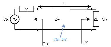
A transmission line is a channel able to carry some information at a very high frequency, so high that parasitics and stray components in the practical realization of the circuit cannot be neglected and must be understood and controlled to have a reliable communication system. Transmission lines can be realized in different ways: on a PCB, using a waveguide, or through a bifilar line; all of these communication media have specific physical and electrical properties and they must be modelled properly before doing any calculation. An important aspect to keep in mind when talking about transmission lines: forget about ground (or earth or reference)! When frequencies are very high you don't have a ground anymore (signal, trace, plane or wire, according to the type of support used to realize the transmission line) but a 'return path': the current in the return path will follow, in fact, the forward path and will not distribute, instead, following the lowest impedance path. This must be taken into consideration especially when designing high-frequency layouts.
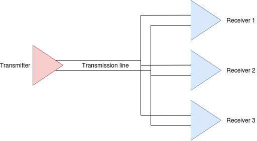
Every communication system is made of a transmitter, one channel and one or more receivers. Transmission line theory focuses mainly on the physics behind the channel and the output stage (input stage) of the transmitter (receiver).
Communication line models
There are various models of a communication channel: distributed C, lumped RC, distributed RC, lumped RLC, and transmission lines. In the table below you can see when it is convenient to use them.
| Model type | R | L | C | Comment |
|---|---|---|---|---|
| Distributed C | 0 | 0 | >0 | Used for very short traces on PCBs or inside a die. The driver must be designed to ensure proper charge of the whole capacitor chain. |
| Lumped RC | >0 | 0 | >0 | Used for short traces where inductance is still negligible but resistance causes edges to be too relaxed. |
| Distributed RC | >0 | 0 | >0 | Used when traces are long/very long but the frequency is not so high to make the parasitic inductance a problem. |
| Lumped RLC | >0 | >0 | >0 | Used when trise and tfall are higher than 2.5x the flight time of the signal over the channel. |
| Transmission line | >0 | >0 | >0 | Used when trise and tfall are lower than 2.5x the flight time of the signal. |

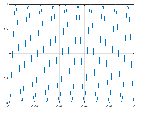
When studying transmission line theory, typically one starts to study the 'lumped RLC' model, which, in the frequency domain, allows one to find a solution for a wave equation in a well-defined media. This solution well describes voltage and current waves along the line, as well as impedance change and reflection phenomena at ends and in correspondence with discontinuities.
Share this page


Comments
Be polite and respectful in the comments section. In case of doubts, read this before posting.
Posted comments ⮧
Comment section still empty.
INDEX
INFO
STATISTICS
NEXT ARTICLE
CONTACTS
SHARE