➔ Index of ⦁ Transmission Lines Theory ⦁
Transmission lines - Part II: The telegraphists' equations
The whole transmission lines theory begins with the study of the telegraphists' equations, based on the RLC model
Derivation
As said in the previous article, the RLC model is the transmission line theory starting point: it is characterized by a few lumped components modelling the main parameters of a small portion of the line; then is possible to describe locally the behaviour of the line and then it can be applied to the whole channel length. Look at the RLC model below, which describes a small line segment and the related equations.
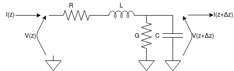
$$R \left[\frac{\Omega}{m}\right], L \left[\frac{H}{m}\right], C \left[\frac{F}{m}\right], G \left[\frac{S}{m}\right]$$ $$ \begin{cases} V(z,t)-V(z+\Delta z,t)=I(z,t)R\Delta z + \frac{dI(z,t)}{dt} L \Delta z \\ I(z,t)-I(z+\Delta z,t)=V(z+\Delta z,t)G\Delta z + \frac{dV(z+\Delta z,t)}{dt} C \Delta z \end{cases} $$ $$ \begin{cases} \frac{V(z,t)-V(z+\Delta z,t)}{\Delta z}=\frac{I(z,t)R\Delta z + \frac{dI(z,t)}{dt} \Delta z}{\Delta z} \\ \frac{I(z,t)-I(z+\Delta z,t)}{\Delta z}=\frac{V(z+\Delta z,t)G\Delta z + \frac{dV(z+\Delta z,t)}{dt} C \Delta z}{\Delta z} \end{cases} $$ $$ \begin{cases} \frac{dV(z,t)}{dz}=I(z,t)R + \frac{dI(z,t)}{dt} L \\ \frac{dI(z,t)}{dz}=V(z,t)G + \frac{dV(z,t)}{dt} C \end{cases} $$
For a lossless line the resistors can be removed from the circuit so R=0Ohm and G=0S. The equations become: $$ \begin{cases} \frac{dV(z,t)}{dz}=\frac{dI(z,t)}{dt} L \\ \frac{dI(z,t)}{dz}=\frac{dV(z,t)}{dt} C \end{cases} $$
Now we can derive the first equation w.r.t. t and the second one w.r.t. z and combine the two, obtaining two wave equations! $$ \begin{cases} \frac{d^2V(z,t)}{dzdt}=\frac{d^2I(z,t)}{dt^2} L \\ \frac{d^2I(z,t)}{dz^2}=\frac{d^2V(z,t)}{dtdz} C \end{cases} $$ $$ \begin{cases} \frac{d^2V(z,t)}{dz^2}=\frac{d^2V(z,t)}{dt^2} L C\\ \frac{d^2I(z,t)}{dz^2}=\frac{d^2I(z,t)}{dt^2} L C \end{cases} $$
The general solution of a wave equation is: $$V(z,t) = V^+(z-v_ft) + V^-(z+v_ft)$$ $$I(z,t) = I^+(z-v_ft) + I^-(z+v_ft)$$ where vf if the phase speed defined as $$v_f = \frac{1}{\sqrt{LC}}$$
Frequency domain
When the wave in the transmission line is time-invariant (constant frequency, constant amplitude, constant initial phase) it is possible to remove the time parameter from the wave equations and to use directly the frequency domain.
$$R \to R, L \to j \omega L, C \to \frac{1}{j \omega C}, G \to G$$ $$ \begin{cases} V(z)-V(z+\Delta z)=-I(z)*(R\Delta z + j \omega L \Delta z) \\ I(z)-I(z+\Delta z)=-V(z+\Delta z)*(G\Delta z + j\omega C \Delta z) \end{cases} $$ $$ \begin{cases} \frac{V(z)-V(z+\Delta z)}{\Delta z}=-\frac{I(z)*(R\Delta z + j\omega L \Delta z)}{\Delta z} \\ \frac{I(z)-I(z+\Delta z)}{\Delta z}=-\frac{V(z+\Delta z)*(G\Delta z + j\omega C \Delta z)}{\Delta z} \end{cases} $$ $$ \begin{cases} \frac{dV(z)}{dz}=-I(z)*(R + j\omega L) \\ \frac{dI(z)}{dz}=-V(z)*(G + j\omega C) \end{cases} $$
For a lossless line the resistors can be removed from the circuit so R=0Ohm and G=0S. The equations become: $$ \begin{cases} \frac{dV(z)}{dz}=-I(z)*(j\omega L) \\ \frac{dI(z)}{dz}=-V(z)*(j\omega C) \end{cases} $$
Substituting respectively I(z) and V(z) in the other formula we obtain: $$ \begin{cases} \frac{dV^2(z)}{dz^2}=-V(z)*(\omega^2 LC) \\ \frac{dI^2(z)}{dz^2}=-I(z)*(\omega^2 LC) \end{cases} $$
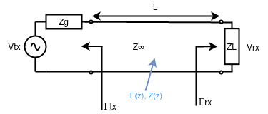
Now the solution can be found, keeping in mind that the generic solution of a 2nd order differential equation is Aebx; k is the so-called wave constant; '0' instead is the starting section of the transmission line. $$ k^2 = \omega^2 L C $$ $$ \begin{cases} V(z)=V_{0}^+e^{-jkz} + V_{0}^-e^{jkz} \\ I(z)=I_{0}^+e^{-jkz} + I_{0}^-e^{jkz} \end{cases} $$ V0+ is the voltage amplitude at the 0 section of the line (typically the end close to the generator) while V0- is the voltage amplitude at the end of the line (typically close to the load). The first term of the voltage (current) solution represents the forward travelling wave (from generator to load) while the second term represents the backward travelling wave (from load to generator). The second term is zero in case of perfectly matched impedance (when the load impedance is the same as the line characteristic impedance), so no reflection is generated at the load. This will be clarified later; for now, just imagine a voltage sine wave with constant amplitude, at a very high frequency, going through a waveguide that can be partially reflected to the generator, according to the type of load at the end of the line.
Now, we can substitute the obtained solution in the previous equation: $$ \begin{cases} \frac{dV(z)}{dz}=-I(z)*(j\omega L) \\ \frac{dI(z)}{dz}=-V(z)*(j\omega C) \end{cases} $$ $$ \begin{cases} \frac{dV_{0}^+e^{-jkz}}{dz}=-I_{0}^+e^{-jkz}*(j\omega L) \\ \frac{dI_{0}^+e^{-jkz}}{dz}=-V_{0}^+e^{-jkz}*(j\omega C) \end{cases} $$ $$ \begin{cases} -jkV_{0}^+e^{-jkz}=-I_{0}^+e^{-jkz}*(j\omega L) \\ -jkI_{0}^+e^{-jkz}=-V_{0}^+e^{-jkz}*(j\omega C) \end{cases} $$ $$ \begin{cases} \frac{V_{0}^+}{I_{0}^+} = \sqrt{\frac{L}{C}} = Z_0 \\ \frac{I_{0}^+}{V_{0}^+} = \sqrt{\frac{C}{L}} = Y_0 \end{cases} \qquad \begin{cases} \frac{V_{0}^-}{I_{0}^-} = -\sqrt{\frac{L}{C}} = -Z_0 \\ \frac{I_{0}^-}{V_{0}^-} = -\sqrt{\frac{C}{L}} = -Y_0 \end{cases} $$
At the end of the calculation one can find the so-called 'characteristic impedance' of the line, which is a value strictly related to the geometry of the medium and its material. This value is very important for transmission lines and should be known before starting any calculation or simulation. It is a constant value representing the ratio between the forward (or backwards) voltage and current waves along the line.
Conclusions
From the solution of telegraphists' equations we found two travellingstanding wave whose maxima change in time but not in space: that's a wave whose amplitude changes in time at well-defined line sections (antinodes) and stays to 0 in correspondence of other sections (nodes).
A line whose impedance is matched will have a voltage sinusoidally changing in time for every line section, and there will be no reflected wave summing up to the forward travelling wave. A line whose impedance is not matched will have a total voltage wave along the line, a standing wave, with maxima that change following z, the spatial variable.
We will analyse all these concepts in the next articles in more detail.
Navigate
Share this page


Comments
Be polite and respectful in the comments section. In case of doubts, read this before posting.
Posted comments ⮧
Comment section still empty.
INDEX
INFO
STATISTICS
PREVIOUS ARTICLE
NEXT ARTICLE
CONTACTS
SHARE