➔ Index of ⦁ Buck Converter ⦁
Buck converter - CCM and DCM
Analysis of the main parameters affecting the operating mode of a buck converter
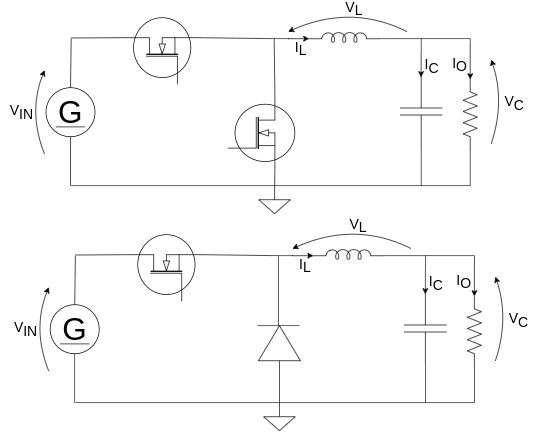
Buck CCM
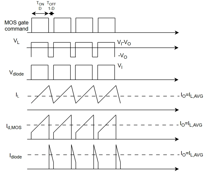
Consider the following image containing the most relevant (and simplified) waveforms as a reference for the next formulas
Let's define $$D = duty \ cycle$$ $$D' = 1-D$$
Finding output-to-input relation in case of a CCM buck is straightforward $$\begin{cases} \Delta I_L = \frac{V_I-V_O}{L}T_{on} = \frac{V_I-V_O}{Lf_{sw}}D\\ \Delta I_L = \frac{-V_O}{L}T_{off} = \frac{-V_O}{Lf_{sw}}D' \end{cases}$$ $$\frac{V_I-V_O}{Lf_{sw}}D = \frac{V_O}{Lf_{sw}}D' \qquad \rightarrow \qquad D = \frac{V_O}{V_I}$$
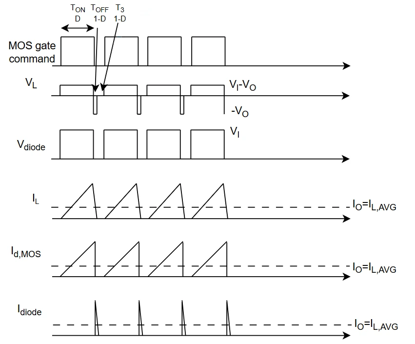
Buck DCM
Here the waveforms of a DCM buck converter: note that there are three intervals in the period, Ton, Toff and T3. The latter is the time interval during which the diode stops recirculating and the voltage across the inductor is zero.
Output-to-input relation in a buck converter operating in DCM is quite more complicated than CCM; here the calculations. Again, D is defined as turn-on time over period and D' is turn-off time over period without the idle time. $$\begin{cases} \Delta I_L = \frac{V_I-V_O}{L}T_{on} = \frac{V_I-V_O}{Lf_{sw}}D\\ \Delta I_L = \frac{-V_O}{L}T_{off} = \frac{-V_O}{Lf_{sw}}D' \end{cases} \qquad \rightarrow \qquad \begin{cases} T_{off} = \frac{V_I-V_O}{V_O}T_{on}\\ I_{L,avg} = \frac{T_{on}+T_{off}}{2T}I_{L,pk} = \frac{V_O}{R}\\ I_{L,pk} = \frac{V_I-V_O}{L}T_{on} \end{cases}$$ $$\begin{cases} T_{off} = \frac{V_I-V_O}{V_O}T_{on}\\ I_{L,avg} = \frac{T_{on}+\frac{V_I-V_O}{V_O}T_{on}}{2T}\frac{V_I-V_O}{L}T_{on} = \frac{V_O}{R}\\ I_{L,pk} = \frac{V_I-V_O}{L}T_{on} \end{cases} \qquad \rightarrow \qquad \begin{cases} T_{off} = \frac{V_I-V_O}{V_O}T_{on}\\ I_{L,avg} = \frac{V_I T_{on}}{2T L I_O} (V_I-V_O)T_{on} = V_O\\ I_{L,pk} = \frac{V_I-V_O}{L}T_{on} \end{cases}$$ $$\begin{cases} T_{off} = \frac{V_I-V_O}{V_O}T_{on}\\ I_{L,avg} = \frac{V_I D^2}{2 f_{sw} L I_O} V_I = V_O(1+\frac{V_I D^2}{2 f_{sw} L I_O})\\ I_{L,pk} = \frac{V_I-V_O}{L}T_{on} \end{cases} \qquad \rightarrow \qquad V_O = \frac{V_I}{1+\frac{2 f_{sw} L I_O}{V_I D^2}} $$
Buck CCM and DCM - Critical inductance
Buck converter can operate in both CCM and DCM, according to input and output voltage, inductor value, switching frequency and load conditions. Remember that all buck converters under light or no load condition will operate in DCM, so it is important to understand when such condition is met and if it is good for our design.
Since requirements are typically fixed (input, output voltage and loads operating points) we can operate on switching frequency and inductor value, so $$\begin{cases} \Delta I_L = \frac{V_I-V_O}{L}T_{on} = \frac{V_I-V_O}{Lf_{sw}}D\\ \Delta I_L = \frac{-V_O}{L}T_{off} = \frac{-V_O}{Lf_{sw}}D' \end{cases}$$ Now we can find the critical inductance whose value set the buck to work in BCM (Boundary mode) $$\overline{i_L} - \frac{\Delta I_L}{2} = 0$$ $$\frac{V_O}{R} - \frac{V_I-V_O}{2Lf_{sw}}D = 0$$ Rearranging terms we can obtain $$L = \frac{V_I-V_O}{2V_O f_{sw}}DR = \frac{V_I-V_O}{2I_O f_{sw}}D = \frac{(1-D)R}{2f_{sw}}$$ To ensure CCM operation, we must choose an inductor larger than the one obtained from the formula, also considering inductor tolerance and saturation.
Share this page


Comments
Be polite and respectful in the comments section. In case of doubts, read this before posting.
Posted comments ⮧
Comment section still empty.
INDEX
INFO
STATISTICS
PREVIOUS ARTICLE
NEXT ARTICLE
CONTACTS
SHARE