➔ Index of ⦁ Buck Converter ⦁
Buck converter - Switching and DC models
Switching and DC models of the buck converter operating in CCM
Switching model
A buck converter is a simple DCDC converter. To extract its steady state DC model and, successively, the AC model, a switching model must be found. Let's do some calculations with components substituted with ideal models (no losses, stray components, saturation effects, voltage drops).
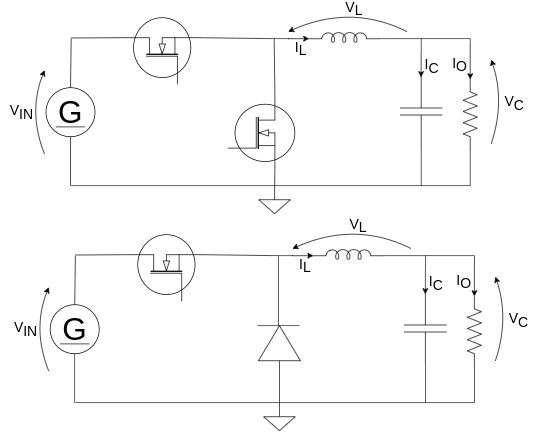
To find a switching model, it's convenient to analyse separately the circuit during the on-time and the off-time.
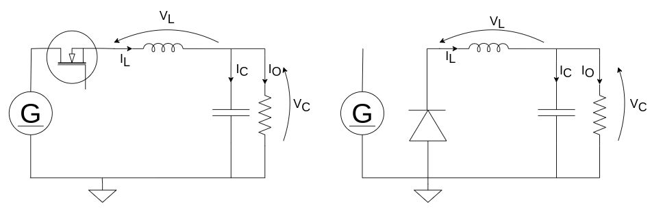
Since there are two reactive elements, let's write their constitutive equations related to voltage and current that must equal 0 over the whole period; it is simply required to calculate the average values between D and D' instants $$\overline{v_L} = D(v_i-v_o) + D'(-v_o) = 0$$ $$\overline{i_C} = D(i_L-\frac{v_o}{R}) + D'(i_L-\frac{v_o}{R}) = 0$$ From the first equation, we can find the input-output relation at steady-state $$D(v_i-v_o) = D'v_o \; \rightarrow \; D = \frac{v_o}{v_i}$$ From the second equation, instead, it is possible to find the inductor average current $$D(i_L-\frac{v_o}{R}) = -D'(i_L-\frac{v_o}{R}) \; \rightarrow \; i_L=\frac{v_o}{R}$$ It's also important to extract the equations related to the input section of the converter. The most relevant is $$i_i = Di_L = Di_o$$
Switching model with losses
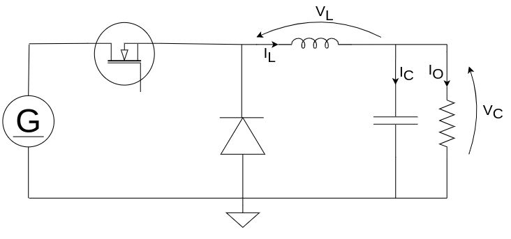
All converters have many non-idealities, so, to refine the model, we have to consider them in our analysis. Let's take a look at the following scheme.
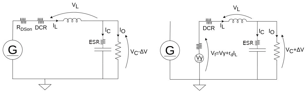
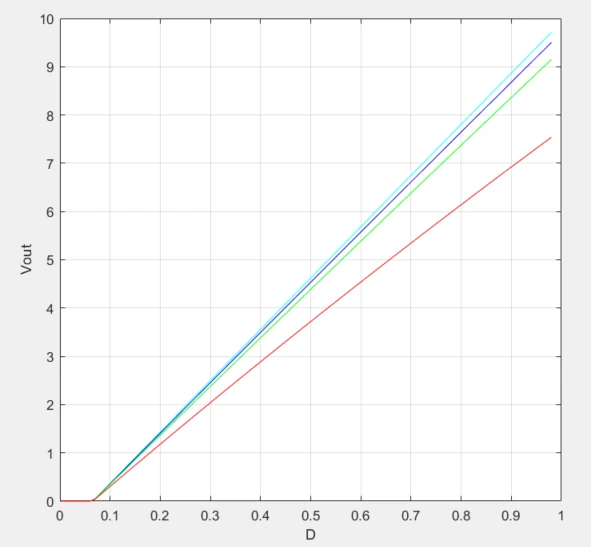
The average values over vL and iC are $$\overline{v_L} = D(v_i-v_o-R_{DSon}i_L-R_{DCR}i_L) + D'(-v_o-v_f-R_{DCR}i_L) = 0$$ $$\overline{i_C} = D(i_L-\frac{v_o}{R}) + D'(i_L-\frac{v_o}{R}) = 0$$ From the first equation, we can find the input-output relation in steady-state, with additional parasitic terms $$D(v_i-v_o-R_{DSon}i_L-R_{DCR}i_L) = D'(v_o+v_f+R_{DCR}i_L) \; \rightarrow \; D=\frac{v_o+v_f+R_{DCR}i_L}{v_i+v_f-R_{DSon}i_L}$$ The effect of increasing resistive losses in MOSFET, inductor and diode voltage drop is shown below: the higher, the lower the output voltage will be. I used a very low load resistance to get high current and so high losses.
From the second equation, we can see that the inductor current is slightly higher than the ideal one when the duty cycle is lower than 0.5 or lower when the duty cycle is higher than 0.5. However, it is difficult to estimate Q - which is the amount of charge taken from the output capacitor causing vo to decrease during turn off (D') - so it is often considered equal to 0C. $$D(i_L-\frac{v_o}{R}+\frac{Qf_{sw}}{D}) = -D'(i_L-\frac{v_o}{R}-\frac{Qf_{sw}}{D}) \; \rightarrow \; i_L = \frac{v_o}{R} + f_{sw}Q\frac{1-2D}{D} $$
DC model
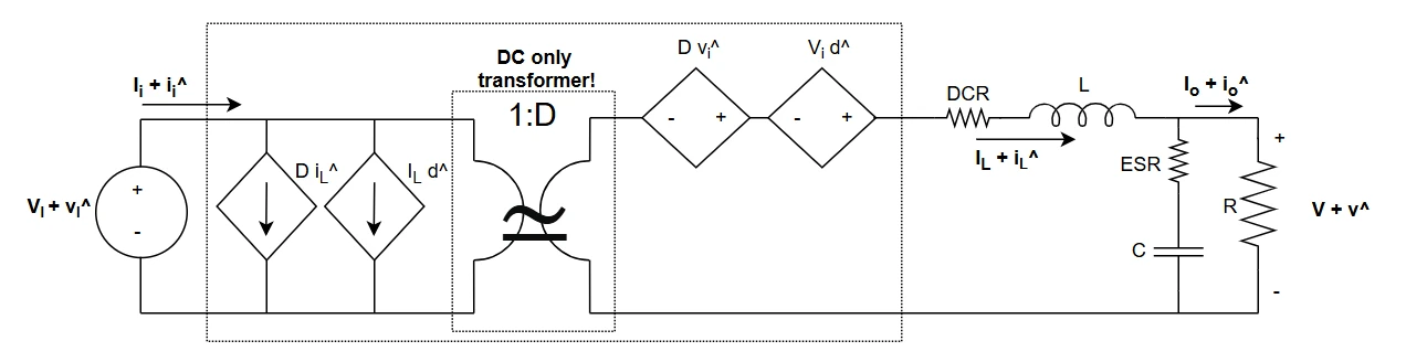
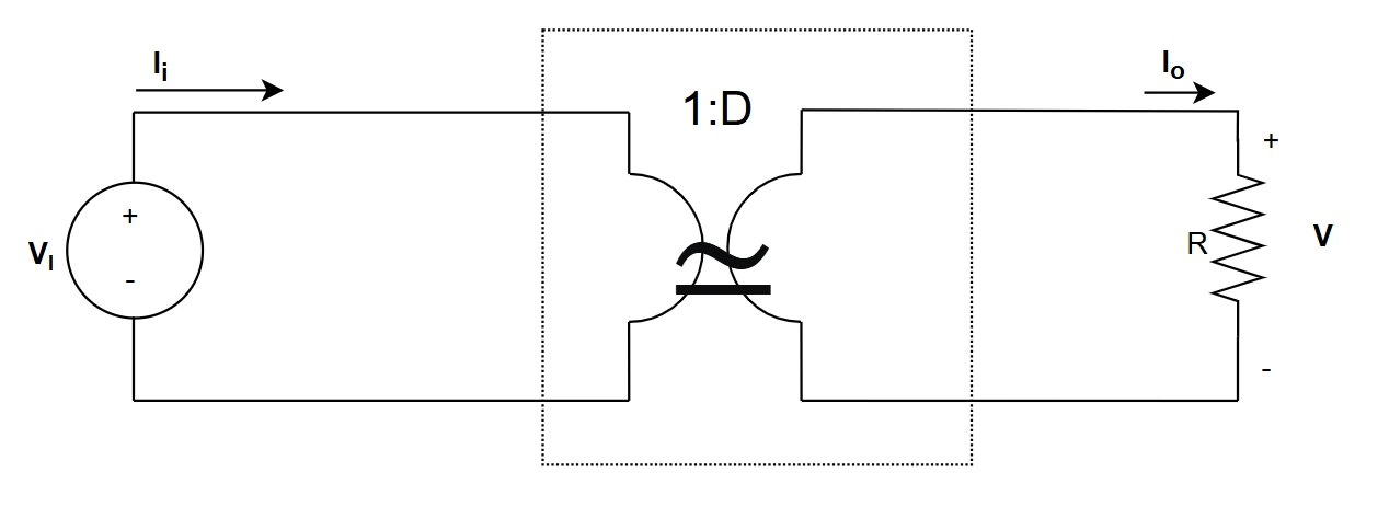
The following image shows the buck DC model, extracted from the switching model through an average operation: the transformer is an ideal DC transformer with a 1:D ratio. From this very simple scheme it's possible to easily calculate all the DC quantities of the converter and find the DC bias point. Note that reactive elements are removed (inductors become short circuits and capacitors open circuits).
Share this page


Comments
Be polite and respectful in the comments section. In case of doubts, read this before posting.
Posted comments ⮧
Comment section still empty.
INDEX
INFO
STATISTICS
PREVIOUS ARTICLE
NEXT ARTICLE
CONTACTS
SHARE