➔ Index of ⦁ Buck Converter ⦁
Buck converter - CCM power dissipation
Power dissipation calculations for a buck operating in CCM
Introduction
From previous articles we saw that the DC model helps to understand the main working principles of the converter, but, it is not so good for power dissipation calculation! Switching losses are not considered, inductor core losses are neglected, and current is assumed to be constant and not pulsed. For proper power dissipation calculation, we shall analyze all the components and the current flowing through them with their real shape.
For RMS calculations, this page is yout friend :)
High side MOSFET losses
Conduction losses
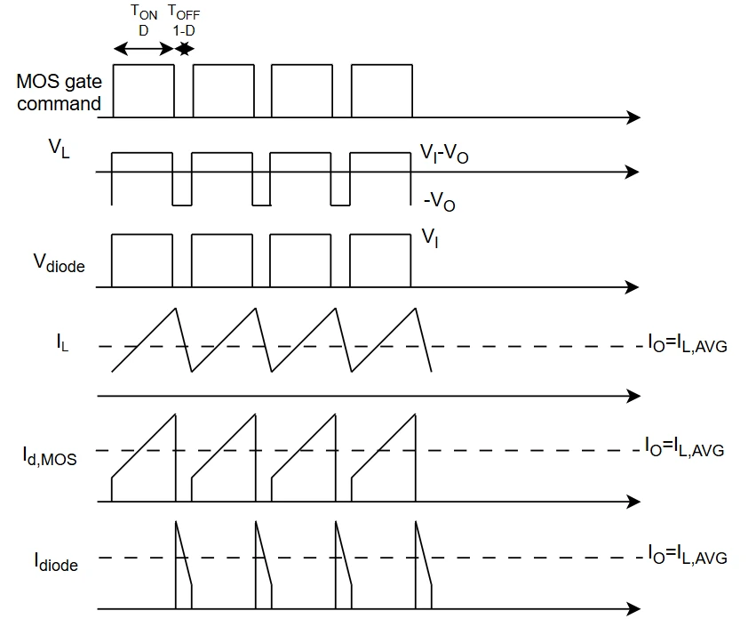
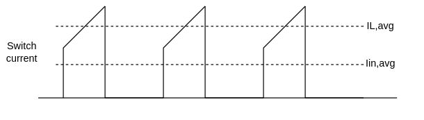
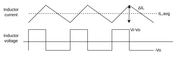
MOSFET sees only the current during turn-on, which has the shape shown in the figure, substantially a trapezoidal pulsed current. We shall find the RMS value of such a waveform to estimate conduction losses. Remember you must use the RDSon at the right junction temperature! For this reason, it is good practice to reiterate the power calculation at different times to get a good result convergence. $$I_{MOS,rms} = \sqrt{\frac{D}{3} \left( (I_{L,avg}-\frac{\Delta I_L}{2})^2 + (I_{L,avg}+\frac{\Delta I_L}{2})^2 + (I_{L,avg}-\frac{\Delta I_L}{2})*(I_{L,avg}+\frac{\Delta I_L}{2}) \right)}$$ $$P_{MOS,cond} = I_{MOS,rms}^2*R_{DSon}$$
Switching losses
MOSFET also has switching losses, highly dependent on driver current capability and gate resistance. It can be estimated as $$P_{MOS,sw} = V_I\frac{(I_{L,avg}-\frac{\Delta I_L}{2})t_{sw,on}}{2T} + \frac{V_I t_{sw,on}}{2T}(I_{L,avg}-\frac{\Delta I_L}{2}) + V_I\frac{(I_{L,avg}+\frac{\Delta I_L}{2})t_{sw,off}}{2T} + \frac{V_I t_{sw,off}}{2T}(I_{L,avg}+\frac{\Delta I_L}{2})$$ tsw,on and tsw,off are the times required for the current and the voltage in and across the MOSFET to reach their target value.
The previous expression can be simplified as $$P_{MOS,sw} = V_I\frac{(I_{L,avg}-\frac{\Delta I_L}{2})t_{sw,on}}{T} + V_I\frac{(I_{L,avg}+\frac{\Delta I_L}{2})t_{sw,off}}{T}$$
Deadtime losses
Since in a buck converter the inductor current always has the same direction (same sign) along the whole period, only the low side switch (in case of synchronous buck topologies) will suffer from deadtime losses so $$P_{MOS,dt} = 0W$$
Leakage losses
When the MOSFET is switched off, it can exhibit an important leakage current, especially at high temperatures. They are often negligible but if you want you can add the following term to your power dissipation estimation. $$P_{MOS,leak} = I_{MOS,leak}*V_I*D'$$
Cds losses
Drain-source parasitic capacitance adds some dissipation to our buck converter. When we work with low-power bucks there such losses are negligible but with high-voltage components they could become relevant! The first thing we have to do is to find the total charge to be dissipated at MOSFET turn-on: in fact, MOSFET is the component that will discharge the DS capacitor during turn-on. Let's calculate the total charge: $$Q_{ds,tot} = \int_{0}^{V_I} C(V) dV$$
If we want to be super-accurate we can account for the diode forward drop, so $$Q_{ds,tot} = \int_{-V_{fd}}^{V_I} C(V) dV$$
The power loss coming from Cds can be estimated as $$P_{MOS,cds} = \frac{Q_{tot}\Delta Vf}{2}$$ The value has a 2 to the denominator since only Cds is discharged through the MOSFET once per cycle.
Gate losses
Gate losses depend on switching frequency. Part of the power is dissipated across the internal push-pull structure of the driver, another part is dissipated by the external gate resistance and finally, the remaining is dissipated by the internal MOSFET gate resistance. Again, let's find the total gate charge $$Q_{g,tot} = \int_{V_{g,OFF}}^{V_{g,ON}} C_{gs}(V) dV + \int_{0}^{V_I} C_{gd}(V) dV$$ Now we can calculate the gate loss due to internal gate resistance only $$P_{MOS,gate} = Q_{g,tot} (V_{g,ON}-V_{g,OFF}) f \frac{R_{g,MOS}}{R_{g,MOS}+R_{g,ext}+R_{drv}}$$
Input capacitor losses
ESR losses
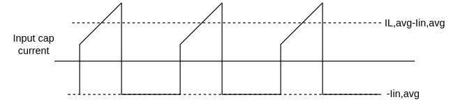
An ideal capacitor will never have a power dissipation different from 0W since it is a fully reactive component. However, internal parasitic elements (which are good for other aspects) cause the component to generate heat. The main term is given by the internal ESR. To estimate it we have to calculate the RMS capacitor current. $$I_{L,avg}-I_{in,avg} = I_{L,avg}-\frac{I_{L,avg}-\frac{\Delta I_L}{2}+I_{L,avg}+\frac{\Delta I_L}{2}}{2}D = I_{L,avg}D'$$ $$I_{Cin,rms} = \sqrt{\frac{D}{3} \left( (I_{L,avg}D'-\frac{\Delta I_L}{2})^2 + (I_{L,avg}D'+\frac{\Delta I_L}{2})^2 + (I_{L,avg}D'-\frac{\Delta I_L}{2})*(I_{L,avg}D'+\frac{\Delta I_L}{2}) \right) + I_{in,avg}^2D'}$$ $$I_{Cin,rms} = \sqrt{DI_{L,avg}^2-2DI_{L,avg}I_{in,avg}+I_{in,avg}^2+\frac{D}{3}\frac{\Delta I_L}{2}}$$ Remember that the ESR you have to use is the one at the component internal temperature, so, like the MOSFET, also this calculation can be done with more than one iteration to have a more accurate result. $$P_{Cin,ESR} = I_{Cin,rms}^2*ESR$$
Leakage losses
Capacitors always have leakage currents (which increase with temperature, ageing, and applied voltage); they cause low losses compared to ESR ones but it is a phenomenon interesting to consider too. $$P_{Cin,leak} = V_I*I_{Cin,leak}$$
Diode losses
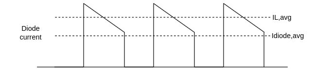
Conduction losses
The main contribution to diode power dissipation is given by conduction (forward) losses, which can be easily estimated as $$I_{diode,rms} = \sqrt{\frac{1-D}{3} \left( (I_{L,avg}-\frac{\Delta I_L}{2})^2 + (I_{L,avg}+\frac{\Delta I_L}{2})^2 + (I_{L,avg}-\frac{\Delta I_L}{2})*(I_{L,avg}+\frac{\Delta I_L}{2}) \right)}$$ $$I_{diode,avg} = \frac{I_{L,avg}-\frac{\Delta I_L}{2}+I_{L,avg}+\frac{\Delta I_L}{2}}{2}D' = I_{L,avg}D'$$ $$P_{diode,fwd} = V_f*I_{diode,avg}+r_d*I_{diode,rms}^2$$
Switching losses
Difficult to be estimated.
Reverse losses
This term is often negligible, however, it gives its contribution that is equal to $$P_{diode,rev} = I_{diode,leak}*V_I*D$$
Output capacitor losses
ESR losses
Like for the input capacitor, also the output capacitor of a buck takes only the AC part of the current in the inductor. The integral of this current (which is the charge stored and/or removed) over the whole period at steady state is always 0. To calculate the output capacitor losses we can find the RMS value of the inductor current, so $$I_{Cout,rms} = \frac{\Delta I_L}{2 \sqrt{3}}$$ The output capacitor power loss is $$P_{Cout,ESR} = I_{Cout,rms}^2*ESR$$
Leakage losses
Again, these losses are negligible; the value is calculated as $$P_{Cout,leak} = V_O*I_{Cout,leak}$$
Inductor losses
DC losses
The DC losses in an inductor is the simplest term to calculate $$P_{L,DC} = I_{L,avg}^2*DCR = (\frac{V_O}{R_O})^2 *DCR$$ Note that the DC loss is proportional to the square of the average current, not the RMS! This is because the superimposed AC term is considered in the AC losses calculation instead. Again, the DCR value at the component temperature must be used.
AC losses
Since the inductor is operated at frequencies where skin effect can occur, you have to consider it. AC losses consider only the AC portion of the whole inductor current and only this part of the current flows at the edges of the wire.
Core losses
Use manufacturer model.
Share this page


Comments
Be polite and respectful in the comments section. In case of doubts, read this before posting.
Posted comments ⮧
Comment section still empty.
INDEX
INFO
STATISTICS
PREVIOUS ARTICLE
NEXT ARTICLE
CONTACTS
SHARE