
Buck main properties
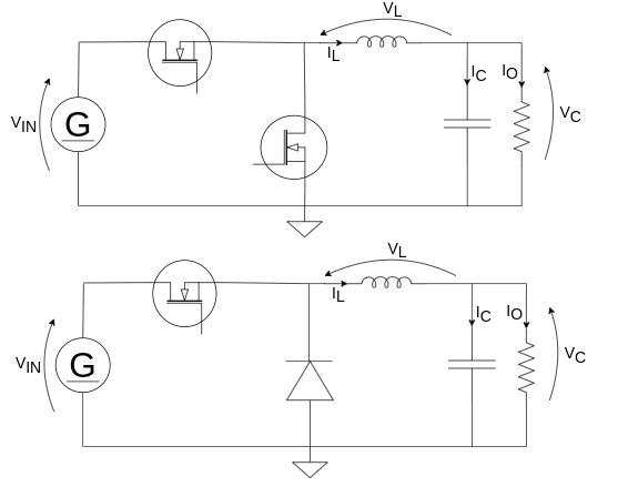
Buck DCDC converter is probably the simplest step-down DCDC topology. It can be easily realized with a high-side switch, a low-side recirculating diode (or switch for synchronous topologies), a properly designed inductor, and input and output capacitors. The main idea is to drive a load applying to an LC filter a square wave between 0V and Vin, whose duty cycle is proportional to the desired output voltage.
Buck converters can be operated in CCM (Continuous Conduction Mode), BCM (Boundary Conduction Mode) or DCM (Discontinuous Conduction Mode) depending on the output voltage, the average current required by the load, the inductance value and the switching frequency. The behaviour and the DC and AC models change sensibly according to the operating point.
CCM
In CCM, the buck converter has an always positive inductor current. This is a good way to drive a buck since RMS and peak-to-peak currents in both passive and switching devices are lower, causing less losses. Moreover, the control scheme is simpler and electromagnetic issues are reduced.
BCM
BCM appear when the off time ends exactly in the instant the inductor current reaches 0A. This mode is used in variable-frequency current-controlled bucks, where the frequency is adjusted to the power needed at the output. However, under high-load conditions, switching losses become the main constraint to the maximum frequency allowed, actually limiting the maximum output power of the converter.
DCM
In DCM, the buck converter has a current that can go to 0 or negative for some time. This happens under light-load conditions too and the control becomes more complex. Given the same output voltage and output power, input capacitor and inductor undergo higher RMS and peak-to-peak currents and higher ripple which leads to higher losses in components and eventually higher electromagnetic noise at the input port. DCM is typically avoided in buck converters.
Applications
Buck converters are used in high voltage - high current applications but also in high current - low voltage applications: they are the preferred supply topology for FPGAs, microcontrollers, CPUs core and/or peripheral supplies since the output voltage is typically very stable, step load transient is good and the noise and the ripple generated by the switching is well filtered by the LC stage.
In high voltage - high current applications, buck converters are typically current-controlled, while in simpler applications the voltage mode (and, eventually, other simple control schemes) is still widely used.
Synchronous buck converters are used as boost too - as you can see, if input and output are swapped, the step-down becomes a step-up converter. This is done in applications where a sort of bidirectionality is required.
Share this page


Comments
Be polite and respectful in the comments section. In case of doubts, read this before posting.