
➔ Index of ⦁ Buck Converter ⦁
Buck converter - Current mode AC model
AC small signal model for a generic buck regulator controlled in current mode (CMC)
Current mode control
Current mode control gives many advantages over the voltage mode control: more stability, no double resonant pole due to the LC output filter, high bandwidth, and better load transient responses; however, the small signal model and the related circuital implementation gain in complexity; let's see the calculations. Refer to the following image as a reference.
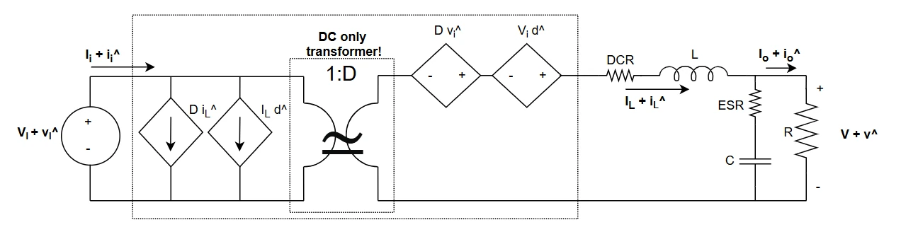
AC small signal model
Starting from Voltage mode control formulas
From the previous article where VMC has been analyzed we can get the formulas $$\begin{cases} \frac{\hat v_O}{\hat i_L} = \frac{R}{1+sCR} \\ \frac{\hat v_O}{\hat d} = \frac{V_I}{s^2 LC + s \frac{L}{R} + 1} \end{cases}$$ For the next calculations also the small signal inductor current expression will be useful, so it is shown here $$\hat i_L = \hat d \frac{V_I}{s^2 LC + s \frac{L}{R} + 1} \frac{1+sCR}{R}$$
Modulation technique dependency
Modulation technique does not enter the Gvd transfer function which is the same for both VMC and CMC, however, it affects the Gvc; in this case, I will consider a peak current mode control, which means that the output of the error amplifier is compared to the peak of the inductor current.
The ramp voltage, generated starting from the inductor current sensing, is equal to the inductor current multiplied by the shunt resistor value and eventually a gain stage. These two terms are collected under Gi parameter. Again, in the following formula, DC components are removed as this is a small signal analysis. $$V_{ramp} + \hat v_{ramp} = G_I (I_L + \hat i_L + \frac{\Delta I_L + \Delta \hat i_L}{2}) \rightarrow \hat v_{ramp} = G_I (\hat i_L + \frac{\Delta \hat i_L}{2})$$ Since we are interested only in the inductor peak current (this is the value I will use to control), I can say that the control voltage is the peak of the ramp voltage. $$\hat v_C = \hat v_{ramp,pk}$$
Inductor current slope dependency
Now I have to find a way to rewrite the previous two expressions, rewriting inductor current and delta inductor current as a function of the duty cycle variation. First of all, I can say that $$\Delta I_L = \frac{V_I-V_O}{L}T_{on} = S_L T_{on} = S_L \frac{D}{f_{sw}}$$ SL is the slope of the current in the inductor, expressed in A/s. Now we can use this steady state equation and the third equation of this page in the previous small signal expression for vramp $$\hat v_{ramp,pk} = \hat v_C = G_I \left (\hat d \frac{V_I}{s^2 LC + s \frac{L}{R} + 1} \frac{1+sCR}{R} + \hat d \frac{S_L}{2 f_{sw}} \right)$$
Substitutions
Since I want to find the Control to Output transfer function, I need a representation for the control voltage to be used instead of duty. As said in the previous article, the power stage function Gvd, Duty to Output function, is always the same for all the possible control schemes and modulation techniques. However, the overall plant transfer function changes sensibly if the modulator changes so it is useful to find the Control to Output function. Rearranging the last expression we obtain $$\hat d = \frac{\hat v_c}{G_I} \frac{2f_{sw}R(s^2 LC + s\frac{L}{R}+1)}{2f_{sw}V_I(1+sCR)+S_L R (s^2 LC + s\frac{L}{R}+1)}$$
Going back to the first equation of this page, we replace d with this duty expression and we get $$\frac{\hat v_O}{\hat v_C} = \frac{V_I}{G_I}\frac{2f_{sw}R}{2f_{sw}V_I(1+sCR)+S_L R (s^2 LC + s\frac{L}{R}+1)}$$ The denominator is $$s^2 LCRS_L + sL S_L + 2V_I f_{fsw}sCR + S_L R + 2V_I f_{fsw}$$ If the switching frequency or the inductance value are sufficiently high, SL is low, in some cases, it can be approximated to 0A/s leading the denominator to be $$2V_I f_{fsw}sCR + 2V_I f_{fsw}$$
Control to Output transfer function
The complete Control to Output transfer function is $$\frac{\hat v_O}{\hat v_C} = \frac{V_I}{G_I}\frac{2f_{sw}R}{2f_{sw}V_I(1+sCR)+S_L R (s^2 LC + s\frac{L}{R}+1)}$$ If the inductor value is very high and the current slope is approximately 0A/s then the transfer function can be approximated to $$\frac{\hat v_O}{\hat v_C} = \frac{R}{G_I (sCR+1)}$$
Power stage transfer functions
List of open loop transfer functions. As you can see they are the same for both VMC and CMC. $$\begin{align} &G_{vd} = \frac{\hat v_O}{\hat d} = \frac{V_I}{s^2 LC + s \frac{L}{R} + 1} \quad Duty-to-Output\\ &G_{vv} = \frac{\hat v_O}{\hat v_I} = \frac{D}{s^2 LC + s \frac{L}{R} + 1} \quad Input-to-Output\\ &G_{id} = \frac{\hat i_L}{\hat d} = \frac{V_I(sCR+1)}{R(s^2 LC + s \frac{L}{R} + 1)}\quad Duty-to-InductorCurrent\\ &G_{iv} = \frac{\hat i_L}{\hat v_I} = \frac{D(sCR+1)}{R(s^2 LC + s \frac{L}{R} + 1)} \quad Input-to-InductorCurrent \end{align}$$ Control-to-Output transfer function with a simple inductor peak current modulator. $$G_{vc} = \frac{\hat v_O}{\hat v_C} = \frac{V_I}{G_I}\frac{2f_{sw}R}{2f_{sw}V_I(1+sCR)+S_L R (s^2 LC + s\frac{L}{R}+1)}$$
Share this page


Comments
Be polite and respectful in the comments section. In case of doubts, read this before posting.
Posted comments ⮧
Comment section still empty.
INDEX
INFO
STATISTICS
PREVIOUS ARTICLE
NEXT ARTICLE
CONTACTS
SHARE