➔ Index of ⦁ Control theory ⦁
Control theory - Dynamic system equations
Let's do some math and find the most relevant equations for a dynamic system
Transfer function
When dealing with dynamic systems it's good to divide them in sub-parts. Each of them can be mathematically represented by a transfer function or a set of differential equations, even if the first representation is often preferred. But what is a transfer function?
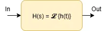
A transfer function is a mathematical function that is used to describe the relation between output and input of a dynamic system or part of it. Usually it is expressed as a Laplace (for continuous time systems) or Z (for discrete time systems) function. $$H(s) = \frac{Y(s)}{U(s)} = \frac{\mathcal L \{y(t)\}}{\mathcal L \{u(t)\}}$$ If the system is not dynamic, the transfer function is not time-dependent and the resolution of input-to-output relation (and every other type) is straightforward. However, if the time variable enters the scene, things get complicated.
From time domain to Laplace domain
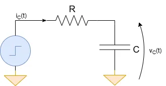
Dynamic systems always contain components whose behaviour is described by differential equations. Let's consider a very simple RC filter: the input is an arbitrary voltage source and the outut is the voltage across the capacitor. Now, let's write down the equations: $$\begin{cases} i_C(t) = C\frac{dv_C(t)}{dt} = C\frac{dv_O(t)}{dt} \\ i_C(t) = \frac{v_I(t)-v_C(t)}{R} \end{cases}$$ $$\frac{dv_O(t)}{dt} + \frac{1}{RC}v_O(t) = \frac{1}{RC}v_I(t)$$ Finding the solution of a differential equation is always very annoying so we can exploit the Laplace transform to simplify the problem. Remember that multiplying by s in the frequency domain is equivalent to differentiate in the time domain. $$sV_O(s) + \frac{1}{RC}V_O(s) = \frac{1}{RC}V_I(s)$$ $$H(s) = \frac{V_O(s)}{V_I(s)} = \frac{1}{RC} \frac{1}{s+\frac{1}{RC}}$$ If we go back to the time domain we obtain an exponential formula but this is not enough to know how the output of the circuit is since the final value of vO(t) depends on the input. If the input is a step function, then we get $$V_O(s) = \frac{V_I}{s} \frac{1}{RC} \frac{1}{s+\frac{1}{RC}}$$ Now, let's move to the time domain (remember the inverse Laplace transform of the product of two functions in the s-domain) $$v_O(t) = \frac{V_I}{RC} \int_0^t u(t-\tau)e^{-\frac{\tau}{RC}}d\tau$$ u(t) is equal to on for each value of t grater than 0 so $$v_O(t) = \frac{V_I}{RC} \int_0^t e^{-\frac{\tau}{RC}}d\tau $$ $$v_O(t) = -V_I e^{-\frac{t}{RC}} + K$$ Since we know that vO(0)=0 (initial condition), then $$v_O(t) = -V_I e^{-\frac{t}{RC}} + V_I$$
To solve this problem we moved into Laplace domain, rewrote input, output and transfer functions as s-functions and moved back in the time domain, without solving any differential equation!
State equation
Let's look to the first differential formula used to describe our very simple RC filter: $$\frac{dv_O(t)}{dt} + \frac{1}{RC}v_O(t) = \frac{1}{RC}v_I(t)$$ We can see that the differential term depends on an output term and an input one: this is an example of state equation and x is the so-called state variable. It can be rewritten in this way: $$\frac{dv_O(t)}{dt} = - \frac{1}{RC}v_O(t) + \frac{1}{RC}v_I(t)$$ The generic form of a state equation of a dynamic system with single state variable is in fact $$\dot x = Ax + Bu$$ where A and B are constants, x is the state variable and u is the input variable. If number of inputs or state variables is higher, then x and u are vectors and A and B are matrices.
The state equation describes completely the system, providing all the necessary information and the engineer must find it before moving into the Laplace domain.
Output equation
State equation is good to know how state variables evolve in time. However, at the end of the design, the engineer is interested in the output of the system. To get this information, the output equation is used.
Output equation has this form: $$y = Cx + Du$$ Again, the output can be dependent on the state and input variables. Now look at the example of the RC filter: which is the output equation? It' very simple! $$y = x$$ In this case, the state variable is also the output variable of the system since we are interested in the capacitor voltage! This is just a simple case but for other systems, C and D can be big matrices and x and u long vectors!
Share this page


Comments
Be polite and respectful in the comments section. In case of doubts, read this before posting.
Posted comments ⮧
Comment section still empty.
INDEX
INFO
STATISTICS
PREVIOUS ARTICLE
NEXT ARTICLE
CONTACTS
SHARE